NuTone 754RBNT Instructions Manual
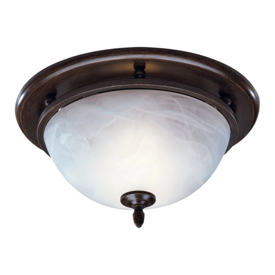
Decorative series ceiling ventilator
Hide thumbs
Also See for 754RBNT:
- Architectural & engineering specifications (1 page) ,
- Selection manual (36 pages)
Table of Contents
Advertisement
Available languages
Available languages
DECORATIVE SERIES
CEILING VENTILATOR
READ AND SAVE THESE INSTRUCTIONS
WARNING
TO REDUCE THE RISK OF FIRE, ELECTRIC
SHOCK, OR INJURY TO PERSONS, OB-
SERVE THE FOLLOWING:
1. Use this unit only in the manner intended by
the manufacturer. If you have questions, con-
tact the manufacturer at the address or tele-
phone number listed in the warranty.
2. Before servicing or cleaning unit, switch power
off at service panel and lock the service dis-
connecting means to prevent power from be-
ing switched on accidentally. When the ser-
vice disconnecting means cannot be locked,
securely fasten a prominent warning device,
such as a tag, to the service panel.
3. Installation work and electrical wiring must be
done by a qualified person(s) in accordance
with all applicable codes and standards, in-
cluding fire-rated construction codes and stan-
dards.
4. Sufficient air is needed for proper combus-
tion and exhausting of gases through the flue
(chimney) of fuel burning equipment to pre-
vent backdrafting. Follow the heating equip-
ment manufacturer's guideline and safety
standards such as those published by the
National Fire Protection Association (NFPA),
and the American Society for Heating, Refrig-
eration and Air Conditioning Engineers
(ASHRAE), and the local code authorities.
5. When cutting or drilling into wall or ceiling, do
not damage electrical wiring and other hid-
den utilities.
6. Ducted fans must always be vented to the out-
doors.
7. NEVER place a switch where it can be
reached from a tub or shower.
8. This unit must be grounded.
9. This unit is U.L. listed. Type I.C. inherently
protected.
!
CAUTION
1. For general ventilating use only. Do not use
to exhaust hazardous or explosive materials
and vapors.
2. This product is designed for installation in
FLAT CEILINGS ONLY. Do not mount this
product in a wall.
3. The light fixture assembly must be mounted
to the fan housing assembly included with this
product. Do not mount the light fixture as-
sembly to a wiring outlet box.
4. To avoid motor bearing damage and noisy
and/or unbalanced impellers, keep drywall
spray, construction dust, etc. off power unit.
5. Please read specification label on product for
further information and requirements.
TYPICAL INSTALLATIONS
HOUSING MOUNTED
DIRECTLY TO JOIST
2x6 (or larger)
Discharge parallel to joists.
HOUSING MOUNTED
TO 2x4 TRUSS
Requires additional framing
for mounting tabs.
Discharge parallel to joists.
HOUSING MOUNTED TO "I" JOIST
Requires additional framing
for mounting tabs.
Discharge parallel to joists.
Additional framing must be a 2x6 (minimum height), at least 9-inches long.
*
Installer: Leave this manual with the homeowner.
Homeowner: Use and Care information on page 4.
MODELS 754RBNT • 754SNNT
HOUSING MOUNTED
TO ADDITIONAL FRAMING
Discharge 90
*
HOUSING MOUNTED TO 2x4
Requires additional framing
for mounting tabs.
Discharge 90
*
HOUSING MOUNTED TO "I" JOIST
Requires additional framing
for mounting tabs.
Discharge 90
Page 1
*
to joists.
0
*
TRUSS
0
to joists.
*
to joists.
0
Advertisement
Table of Contents

Related Manuals for NuTone 754RBNT


Summary of Contents for NuTone 754RBNT
-
Page 1: Typical Installations
Discharge parallel to joists. Additional framing must be a 2x6 (minimum height), at least 9-inches long. Installer: Leave this manual with the homeowner. Homeowner: Use and Care information on page 4. MODELS 754RBNT • 754SNNT Page 1 HOUSING MOUNTED TO ADDITIONAL FRAMING Discharge 90 to joists. -
Page 2: Existing Construction
2. In attic, position mounting brackets against joist. Trace outline of housing on ceiling material. outward. Lift 3. Set housing aside and cut ceiling opening slightly larger than marked. MODELS 754RBNT • 754SNNT New Construction Existing Construction Page 2... -
Page 3: Connect The Wiring
6. Restore electrical power and check operation of the unit. MODELS 754RBNT • 754SNNT R E D B L U W H T L I G H T ( W H I T E ) -
Page 4: Service Parts
The motor is permanently lubricated. Do not oil or disassemble motor. SERVICE PARTS KEY PART NO. DESCRIPTION 97016702 Glass Shade 97016701 Shade Mounting Hardware (754RBNT) 97016704 Shade Mounting Hardware (754SNNT) 99260428 Motor Nut, #6-32 Hex (2 req.) 99150618 Grille Screw 99080522... -
Page 5: Instalaciones Típicas
A la persona que realiza la instalación: Deje este manual con el dueño de la casa. Al dueño de la casa: Las instrucciones de operación y limpieza se encuentran en la MODELOS 754RBNT • 754SNNT Página 5 CUBIERTA MONTADA EN UNA ESTRUCTURA ADICIONAL Descarga a 90º... -
Page 6: Instalación De La Cubierta
Levante la cubierta hasta que las aletas entren en contacto con la cara inferior de la vigueta. Marque el orificio con forma de cerradura de ambas abrazaderas MODELOS 754RBNT • 754SNNT INSTALACIÓN DE LA CUBIERTA (continuación) Construcción nueva... -
Page 7: Conexión Eléctrica
6. Restaure eléctrica y verifique la operación de la unidad. MODELOS 754RBNT • 754SNNT DIAGRAMA ELÉCTRICO R O J O A Z U L B L A N C O L A M P . -
Page 8: Uso Y Cuidado
El motor lleva lubricación permanente. No lo enaceite o desarme. PIEZAS DE SERVICIO CLAVE N PIEZA DESCRIPCIÓN 97016702 Pantalla de Vidrio 97016701 Equipo de Montaje de Pantalla (754RBNT) 97016704 Equipo de Montaje de Pantalla (754SNNT) 99260428 Tuerca del Motor, #6-32 Hex (2 req.) 99150618 Tornillo de Rejilla 99080522...
Need help?
Do you have a question about the 754RBNT and is the answer not in the manual?
Questions and answers