
Summary of Contents for ADLINK Technology NeuronBot
- Page 1 NeuronBot User’s Manual Rapid Robotic Development Platform Manual Rev.: Revision Date: October 29, 2020 Part Number: 50-1Z334-1000...
- Page 2 Preface Copyright Copyright © 2020 ADLINK Technology, Inc. This document contains proprietary information protected by copyright. All rights are reserved. No part of this manual may be reproduced by any mechanical, electronic, or other means in any form without prior written permission of the manufacturer.
-
Page 3: Table Of Contents
NeuronBot Table of Contents Preface ..........................ii List of Figures ........................v Introduction ........................ 7 Product Overview ...................... 7 2.1. Main Specifications ..................... 7 2.2. Power Specifications ....................9 2.3. Software ........................9 2.4. Package Contents ...................... 9 2.5. Optional Accessories ....................9 2.6. -
Page 4: Preface
Safety Instructions ....................76 Getting Service ......................77 Preface... -
Page 5: List Of Figures
NeuronBot List of Figures Figure 1: Front View Dimensions (No Accessories) ................10 Figure 2: Front View Dimensions (with Accessories) ................10 Figure 3: Side View Dimensions (No Accessories) ................11 Figure 4: Side View Dimensions (with Accessories) ................11 Figure 5: Front View Layout (No Accessories) ..................12 Figure 6: Front View Layout (with Accessories) ..................13... - Page 6 This page is intentionally left blank. Preface...
-
Page 7: Introduction
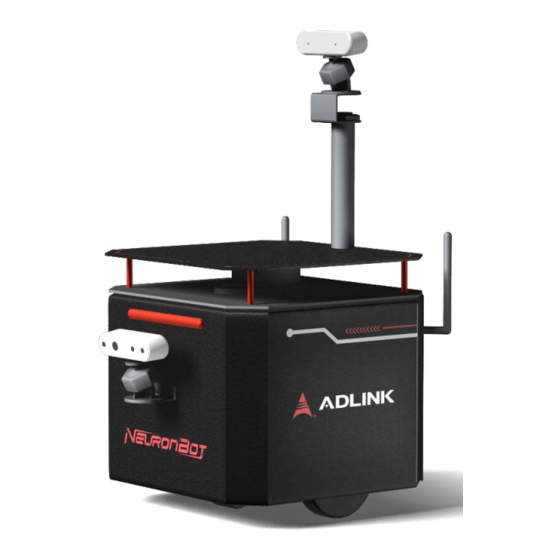
NeuronBot 1. Introduction The NeuronBot is an affordable, miniature, autonomous rapid robotic development platform with integrated computational unit, LiDAR sensor, high payload capacity and dynamic motion capability, and is ideal for enabling a wide range of exciting research, training, and educational activities. - Page 8 NeuronBot NB-SK Mechanical Payload 3 kg Wheel Diameter 83 ±2 mm Wheel Center Distance 218 ±3 mm Translational Velocity Max. 0.6 m/s Rotational Velocity Max. 0.6 m/s Climbing Threshold 0° ±1° Actuator DC carbon-brush motor (1:139) Dimensions 260 x 270 x 260 mm (10.24 x 10.63 x10.24 inches) Weight 7.8 kg...
-
Page 9: Power Specifications
1x Quick Start Guide Cable 1x DisplayPort to HDMI adapter cable 2.5. Optional Accessories ADLINK provides all the necessary parts and accessories for NeuronBot. You can purchase additional accessories according to your needs. Item Description Camera Intel® RealSense™ Depth Camera D435... -
Page 10: Mechanical Dimensions
2.6. Mechanical Dimensions Note: All are dimensions shown in millimeters. 2.6.1. Front View Dimensions Holes for M4 screws Figure 1: Front View Dimensions (No Accessories) Note: M4 screw holes are for attaching the front camera bracket to the chassis (see Front Camera Installation on page 21). -
Page 11: Figure 3: Side View Dimensions (No Accessories)
NeuronBot 2.6.2. Side View Dimensions 266.5 Figure 3: Side View Dimensions (No Accessories) Figure 4: Side View Dimensions (with Accessories) Product Overview... -
Page 12: System Layout
2.7. System Layout 2.7.1. Front View Layout (No Accessories) Figure 5: Front View Layout (No Accessories) Status LED bar Wheel Screw holes for front LIDAR component camera bracket Wheel Product Overview... -
Page 13: Figure 6: Front View Layout (With Accessories)
NeuronBot 2.7.2. Front View Layout (with Accessories) Figure 6: Front View Layout (with Accessories) Support plate RealSense camera Front bracket for RealSense Top-side stand-off camera RealSense camera Product Overview... -
Page 14: Figure 7: Rear View Panel Layout (Rear Cover Attached)
2.7.3. Rear View Layout Figure 7: Rear View Layout Battery status indicator Rear cover knob Power button Rear cover GPIO connector Note: The rear cover is attached to the chassis by two magnetic fasteners. To access the rear panel I/O, remove the rear cover by grasping the knob and gently pulling the cover away from the chassis. -
Page 15: Figure 8: Rear View I/O Layout (Rear Cover Not Attached)
NeuronBot 2.7.4. Rear View I/O Layout (Rear Cover Removed) Figure 8: Rear View I/O Layout (Rear Cover Not Attached) USB 3.0 ports (4x) LAN ports (2x) Magnetic fasteners for rear DisplayPorts (3x) cover USB 2.0 ports (4x) Product Overview... -
Page 16: Hardware Accessory Installation
3. Hardware Accessory Installation This section describes how to install the following accessories on the NeuronBot: • Support plate • Intel ® RealSense™ Depth Camera D435 Note: You can install up to two cameras according to your needs. Intel® RealSense™... - Page 17 NeuronBot 2. Align the holes on the support plate with the stand-offs and place the support plate on top of the stand-offs. 3. Attach the screws to the support plate. Hardware Accessory Installation...
-
Page 18: Top Camera Installation
3.2. Top Camera Installation 1. Attach the support plate to the NeuronBot. a. Attach the support plate standoffs to the NeuronBot. b. Attach the large, top-side stand-off to the support plate. Hardware Accessory Installation... - Page 19 NeuronBot c. Place the attached stand-off and support plate on the NeuronBot. d. Align the holes on the support plate with the stand-offs and attach the screws. Hardware Accessory Installation...
- Page 20 2. Attach the top bracket to the large, top-side stand-off. 3. Assemble the camera by screwing the camera head onto the camera base. 4. Attach the assembed camera to the top bracket using the adhesive sticker provided with the NeuronBot. Hardware Accessory Installation...
-
Page 21: Front Camera Installation
1. Attach the front bracket to the NeuronBot. 2. Assemble the camera by screwing the camera head onto the camera base. 3. Attach the assembled camera to the front bracket using the adhesive sticker provided with the NeuronBot. Hardware Accessory Installation... -
Page 22: Top Camera Cable Routing
3.4. Top Camera Cable Routing 1. Connect a USB cable to a USB 3.0 port on the rear I/O panel (see Rear View Layout on page 14). 2. Route the cable through the top-side stand-off, from the bottom of the support plate to the top bracket, and connect the USB cable to the top camera. -
Page 23: Front Camera Cable Routing
NeuronBot 3.5. Front Camera Cable Routing 1. Remove the top cover from the chassis. Note: Ensure that the LiDAR module is disconnected from the I/O before removing the top cover. a. Remove the screws that secure the top cover to the chassis. - Page 24 2. Remove the plug from the front opening of the chassis. 3. Connect a USB cable to a USB 3.0 port on the rear I/O panel (see Rear View I/O Layout on page 15). 4. Route the cable to the front of the chassis internally and connect the cable to the front-mounted camera. Note: When connecting the RealSense camera, do not allow the connector cable to pass over the main board.
-
Page 25: Controls And I/O
Power Button The power button is a non-latched push button located on the rear side of the NeuronBot (see Rear View Layout on page 14). The system powers on when the button is pressed and the LED status bar lights (see Front View Layout on page 12). -
Page 26: Operating Instructions
Before installation, you must create an Ubuntu USB installation stick on a Windows PC. To install Ubuntu and ROS on the NeuronBot, you need to connect a USB keyboard, mouse, and monitor to the DisplayPort connector. ROS has many different distributions, each requiring a different Ubuntu version. For example, if you want to use ROS 1 Kinetic, you have to install Ubuntu 16.04. - Page 27 5.1.2. ROS Installation After installing Ubuntu on the NeuronBot, follow the instructions below to set up the ROS environment. 5.1.2.1. ROS Distributions Please visit the ROS official website to get the latest installation guide for both ROS 1 and ROS 2.
- Page 28 you have installed Melodic, Dashing, and Eloquent, and you want to run ROS applications with Eloquent, you can start with the following: source /opt/ros/eloquent/setup.bash 5.1.2.2. Verifying the ROS 1 Installation To verify the ROS 1 installation, you need to open three terminals and execute the following commands. Note: <YOUR_ROS_DISTRO>...
- Page 29 NeuronBot After installation, you can execute turtlesim_node again to check that the turtlesim program opened successfully. • Terminal 2: Load the ROS 2 environment and use the arrow keys to tele-opreate the turtle source /opt/ros/<YOUR_ROS_DISTRO>/setup.bash ros2 run turtlesim turtle teleop key 5.1.2.4.
- Page 30 5.1.3. Linux Tools Installation After the ROS environment is verified, it is recommended that you install the following tools for help developing ROS applications. sudo apt update && sudo apt install -y \ build-essential \ cmake \ git \ libbullet-dev \ python3-colcon-common-extensions \ python3-flake8 \ python3-pip \...
- Page 31 NeuronBot 5.1.4.2. Menu Usage After installation, the terminal will display the following menu: ************ Neuron Startup Menu for ROS ************* * Usage: To set ROS env to be auto-loaded, please assign ros_option in ros_menu/config.yaml ****************************************************** 0) Do nothing 1) ROS 1 melodic...
- Page 32 • Enable the menu: menu_enable: "true" to enable the menu, “false” to disable the menu • Set the default ROS option: ros_option: "menu" to show all the options of the menu. Note: You can also set an option number to this variable and the menu will automatically apply the option every time you open the terminal.
- Page 33 Note: Remember to remove the Neuron Startup Menu configuration in ~/.bashrc. 5.1.5. NeuronBot Setup NeuronBot source code is available on our GitHub. Visit the following webpage to get the latest updates: https://github.com/Adlink-ROS/neuronbot2 5.1.5.1. Getting the NeuronBot Software For ROS 1 Melodic: 1.
- Page 34 Use catkin_make to compile NeuronBot under the ROS 1 Melodic environment. After successful compilation, the NeuronBot environment is created. Afterward, if you want to run NeuronBot applications, you have to “source” setup.bash in ROS 1 Melodic and the NeuronBot workspace.
-
Page 35: Remote Control And Monitoring
ROS 1 Remote Control Settings In ROS 1, the IP address is needed to tell ROS 1 applications (e.g., rviz and rqt) where to find NeuronBot. Therefore, when you want to connect NeuronBot remotely, make sure that ROS_MASTER_URI and ROS_IP are set correctly. - Page 36 ROS_IP=192.168.50.110 To make this easier, you can set up the ADLINK Neuron Startup Menu on the NeuronBot and computer. Use the following command to edit the Neuron Startup Menu. Here, we used gedit as as the editor; however, you can use any editor you want.
- Page 37 To address this, you can connect to an SSH server, which is a secure shell for network connections. An SSH server will allow you to remotely connect to a NeuronBot for the secure transfer of files or to perform administrative tasks like teleoperating the NeuronBot.
- Page 38 RVIZ in a new terminal using a local terminal on a computer. Note: “Session” means a window in a single terminal with an SSH connection to a NeuronBot. You can confirm your session number at the bottom of the window.
- Page 39 2. Set up the SSH connection to access the NeuronBot remotely on your computer. ssh –X ros@192.168.50.26 3. Start Byobu to run multiple sessions on a single SSH connection. Note: “Session” means a window in a single terminal with an SSH connection to a NeuronBot. byobu • Session 0: Source the environment.
- Page 40 If the listener successfully subscribed to the messages, then the remote control parameters have been successfully set for ROS 1. 5.2.7. ROS 2 Remote Control Verification To verify that remote control parameters have been set up for ROS 2, you can run a talker on NeuronBot and a listener on the computer. Terminal 1: ...
- Page 41 NeuronBot Note: “Session” means a window in a single terminal with an SSH connection to a NeuronBot. byobu • Session 0: Source the environment. source /opt/ros/<YOUR_ROS2_DISTRO>/setup.bash 5. Start the talker. After starting the talker on NeuronBot, it will publish “hello world” messages continuously.
-
Page 42: Ros 1 Applications
Note: This launch file contains multiple nodes and enables communication between the motor controller, laser SLAM, and all NeuronBot TF definitions. If you end the node with ctrl + c, remember only to press once and allow it to shut down automatically. The rplidarNode node requires some time to shut down the serial port. - Page 43 0.4 m/s and the angular speed to 0.4 rad/s. Press k or s to immediately stop. rosrun teleop_twist_keyboard teleop_twist_keyboard Figure 4-1-3-1: teleop_twist_keyboard Terminal 2: Set up the environment by setting ROS_MASTER_URI to the NeuronBot’s IP address. source /opt/ros/<YOUR_ROS1_DISTRO>/setup.bash export $ROS_MASTER_URI=http://192.168.50.26:11311 11. Launch RViz. rviz ...
- Page 44 13. Select TF and click OK to display the frames. 14. Click the Add button again in the lower left. 15. Click the By topic tab to display available topics. 16. Select LaserScan and click OK to display 2D LiDAR data. Operating Instructions...
- Page 45 For example, in ROS 1 Melodic, we added a “source” command so that every time a new session and terminal is opened, the menu automatically loads the NeuronBot workspace environment. This way, there is no longer a need to “source” ROS and NeuronBot anymore.
- Page 46 After getting a static map, running a SLAM package is not recommended due to its computational load. This section describes how to use an AMCL package to locate the NeuronBot using a previously generated map and existing laser scan. This will allow you to move the NeuronBot from one location to a specified destination.
- Page 47 NeuronBot 4. Rename Group to Global Map. 5. Click OK. 6. Click the Add button in the lower left again. 7. Rename Map to Costmap. 8. Drag Costmap into Global Map and set the parameters as follows. List of Figures...
- Page 48 9. Click Add, rename Path to Planner, drag Planner into Global Map, and set the parameters as follows. 10. Click Add, rename Group to Local Map, and click OK. 11. Click Add, rename Map to Costmap, drag Costmap into Local Map, and set the parameters as follows. 12.
- Page 49 14. Click Add, select Odometry, click OK, and set the parameters as follows. 15. Perform pose estimation. a. Click "2D Pose Estimate", and set the pose estimation to the approximate location of the NeuronBot on the map. Note: By default, the localization package will initialize the NeuronBot at (x,y)=(0,0); i.e., the same as the starting position when the mapping process started.
-
Page 50: Ros 2 Applications
~/neuronbot2_ros1_ws/src/neuronbot2/neuronbot2_nav/rviz/view_navigation.rviz 5.4. ROS 2 Applications This section describes how to build, compile, and run several applications with ROS 2 on NeuronBot, and provides instructions on configuring NeuronBot for the following applications: Teleoperation: Move the NeuronBot using a keyboard and scan the surrounding environment using 2D LiDAR. - Page 51 Note: This launch file contains multiple nodes and enables communication between the motor controller, laser SLAM, and all NeuronBot TF definitions. If you end the node with ctrl + c, remember only to press once and allow it to shut down automatically. The rplidarNode node requires some time to shut down the serial port.
- Page 52 source /opt/ros/<YOUR_ROS2_DISTRO>/setup.bash 9. Launch RViz. rviz2 RViz2: 10. Click the Add button in the lower left. 11. Select TF and click OK to display the frames. 12. Click the Add button again in the lower left. 13. Click the By topic tab to display available topics. 14.
- Page 53 For example, in ROS 2 Dashing, we added a “source” command so that every time a new session and terminal is opened, the menu automatically loads the NeuronBot workspace environment. This way, there is no longer a need to “source” ROS and NeuronBot anymore.
- Page 54 • Session 2: to decrease the linear to 0.3 m/s as well as angular speed to 0.2 rad/s, and then drive the NeuronBot around using the keyboard driver. After mapping the environment, remember to save the before closing the Slam Toolbox.
- Page 55 After getting a static map, running a SLAM package is not recommended due to its computational load. This section describes how to use an AMCL package to locate the NeuronBot using a previously generated map and existing laser scan. This will allow you to move the NeuronBot from one location to a specified destination.
- Page 56 RViz2: 3. Click the Add button in the lower left. 4. Rename Group to Global Planner. 5. Click OK. 6. Click the Add button in the lower left again. 7. Rename Map to Global Costmap. Operating Instructions...
- Page 57 NeuronBot 8. Drag Global Costmap into Global Planner and set the parameters as follows. 9. Click Add, select Path, drag Path into Global Planner, and set the parameters as follows. 10. Click Add, select Group, click OK, and then rename Group to Local Planner.
- Page 58 16. Set the estimation. a. Click "2D Pose Estimate", and set the estimation to the approximate location of the NeuronBot on the map. Note: By default, the localization package will initialize the NeuronBot at (x,y)=(0,0); i.e., the same as the starting position when the mapping process started. You can also manually assign the starting position by using the "set 2D pose estimation"...
- Page 59 NeuronBot Tip: You can save time by opening the RViz2 config file in ~/neuronbot2_ros2_ws/src/neuronbot2/neuronbot2_nav/rviz/nav2_default_view.rviz List of Figures...
-
Page 60: Troubleshooting
6.1. Self-diagnosis This section illustrates how to determine whether your NeuronBot is running normally or abnormally. The test scripts provided in this section leverage the NeuronBot ROS 1 package. Note: Ensure that you download and build the latest source code before troubleshooting. -
Page 61: Faq
NeuronBot If the LiDAR-generated red lines which do not appear, try the following: 1. Perform LiDAR initialization again. For details, see NeuronBot Setup on page 33. 2. Disconnect and reconnect all USB cables and restart NeuronBot. 3. Execute the following command: ls /dev/rplidar -l You should find /dev/rplidar linked to /dev/ttyUSB*. - Page 62 /opt/ros/<YOUR_ROS_DISTRO>/setup.bash 3. Q: What causes “[xxx.launch] is neither a launch file …”? A: The NeuronBot ROS 1 environment may not be sourced. Source the environment to fix this issue. source ~/neuronbot2_ros1_ws/devel/setup.bash 4. Q: What causes “Package ‘neuronbot2_xxx’ not found …”? A: The NeuronBot ROS 2 environment may not be sourced.
- Page 63 For ROS 1, ensure that ROS_MASTER_URI and ROS_IP are correctly set on both the host computer and NeuronBot. • For ROS 2, ensure that ROS_DOMAIN_ID is correctly set on both the host computer and NeuronBot. See ROS 1 Remote Control Settings and ROS 2 Remote Control Settings for details on setting environment variables.
-
Page 64: System Backup And Restore
7. System Backup and Restore This section explains how to create a bootable USB drive for backing up and restoring the system. 7.1. Preparation 7.1.1. Clonezilla Clonezilla is an open source tool for backup and restoration. 1. Download the stable version from the official website: https://clonezilla.org/downloads.php 2. - Page 65 NeuronBot The ISOHybrid image detected window will appear. 6. Select Write in ISO image mode (Recommended) and click OK. A warning message will appear to notify you that all data on the USB drive will be erased. 7. Click OK.
- Page 66 Rufus will being writing to the USB drive. When the process is completed, the Status will show READY. 8. Click CLOSE to exit the program. System Backup and Restore...
-
Page 67: Full Disk Backup
4. Go to the Save & Exit tab and select UEFI: <YOUR-CLONEZILLA-USB-DRIVE>. NeuronBot will boot using the inserted Clonezilla USB drive. The screen will display the Clonezilla GNU GRUB. 5. Select Clonezilla live (To RAM, boot media can be removed later) in the menu that appears. - Page 68 6. Select your language. 7. Select Start_Clonezilla. 8. Select device-image (for creating a backup image). System Backup and Restore...
- Page 69 NeuronBot Tip: Use the arrow keys to change options and press the spacebar to confirm your selection. List of Figures...
- Page 70 9. Select local_dev (to store the image on the USB drive). 10. (Optional) Insert another USB drive to store the image. To save the image onto the same USB drive as Clonezilla, press Ctrl-C. 11. Select the disk where you want to store the image. Tip: You can use the Clonezilla USB drive if it has enough free space.
- Page 71 NeuronBot 12. Press the right arrow key to highlight <Done>, and then press the spacebar to confirm. 13. Select Beginner (to use default options). 14. Select savedisk (to back up the entire disk). 15. Specify a name for the image file.
- Page 72 16. Select the disk where you want to save the image file. 17. Select the default compression option. 18. Select -sfsck to skip checking the file system. Note: If you want to check the file system, select -fsck. 19. Select Yes to check whether the saved image is restorable. 20.
- Page 73 NeuronBot 21. Select -senc to skip image encryption. 22. Press y to confirm savedisk. Clonezilla will back up the disk backup to an image file. Please wait while the disk is backed up. List of Figures...
-
Page 74: Full Disk Restoration
7.3. Full Disk Restoration Restoring the system from a backup image is similar to the Full Disk Backup process. The following instructions contain only the steps that differ from the backup process. 1. Select the disk where the image is saved. 2. - Page 75 NeuronBot 5. Select Yes to check the image before restoring (recommended if the image has not been used for a long time); otherwise, choose No to skip the check. Clonezilla will ask you to confirm (the disk to be restored will be erased).
- Page 76 8. Safety Instructions For user safety, please read and follow all instructions marked on the product and documentation before handling/operating the device. Please retain all safety and operating instructions for future reference. • Read these safety instructions carefully • Keep this User‘s Manual for future reference •...
- Page 77 5215 Hellyer Avenue, #110, San Jose, CA 95138, USA Tel: +1-408-360-0200 Toll Free: +1-800-966-5200 (USA only) Fax: +1-408-360-0222 Email: info@adlinktech.com ADLINK Technology (China) Co., Ltd. Address: 300 Fang Chun Rd., Zhangjiang Hi-Tech Park, Pudong New Area Shanghai, 201203 China Tel: +86-21-5132-8988 Fax: +86-21-5132-3588 Email: market@adlinktech.com...
Need help?
Do you have a question about the NeuronBot and is the answer not in the manual?
Questions and answers