
Related Manuals for ADJ PIXIE DRIVER 2000

Summary of Contents for ADJ PIXIE DRIVER 2000
- Page 1 PIXIE DRIVER 2000 User Manual US SKU#: PIX142 EU SKU#: 1226200064 UPC#: 818651027860 ITF-14#: 10818651027867...
- Page 2 All non-ADJ Products, LLC brands and product names are trademarks or registered trademarks of their respective companies. ADJ Products, LLC and all affiliated companies hereby disclaim any and all liabilities for property, equipment, building, and electrical damages, injuries to any persons, and direct or indirect economic...
-
Page 3: Table Of Contents
TABLE OF CONTENTS Introduction Features | Warranty Registration Safety Guidelines Overview Installation Driver Output Limitations RGB Pixel Control System Menu Limited Warranty Dimensional Drawings Specifications Accessories... -
Page 4: Introduction
Introduction: Congratulations on your purchase of the ADJ Pixie Driver 2000! This device has been designed to provide easy and versatile control options specifically for the ADJ Pixie Strip 30, 60, and 120 series, and to perform reliably for years when the guidelines in this booklet are followed. Please read and understand the instructions in this manual carefully and thoroughly before attempting to operate this device. -
Page 5: Features | Warranty Registration
1 x 10-foot (3m) 4-pin power / data cable WARRANTY REGISTRATION The Pixie Driver 2000 carries a 2 year limited warranty. Please fill out the enclosed warranty card to validate your purchase. All returned service items, whether under warranty or not, must be freight pre- paid and accompanied by a return authorization (R.A.) number. -
Page 6: Safety Guidelines
SAFETY GUIDELINES For Your Own Personal Safety, Please Read and Understand This Manual Completely Before You Attempt To Install Or Operate This Unit! • Be sure to save the packing carton in the unlikely event the device may have to be returned for service •... -
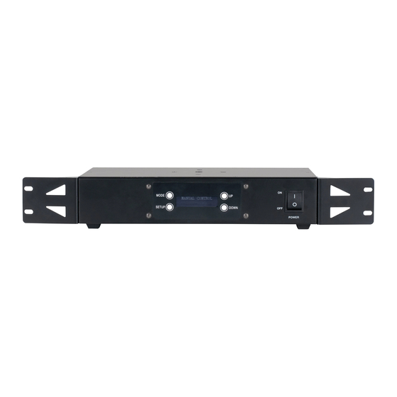
Page 7: Overview
OVERVIEW 1. Setup Button 8. Safety Cable Attachment Point 2. Mode Button 9. 10A Output Fuses 3. LCD Screen 10. 3A Input Fuse 4. Up Button 11. Power In 5. Down Button 12. Kling-Net/Art-Net Ports 6. Main Power Switch 13. 4-pin Outlet Sockets 7. -
Page 8: Installation
INSTALLATION FLAMMABLE MATERIAL WARNING! Keep drive a minimum of 5.0 feet (1.5m) away from flammable material and/or pyrotechnics. ELECTRICAL CONNECTIONS A qualified electrician should be used for all electrical connections and/or installations. DO NOT INSTALL THE DEVICE IF YOU ARE NOT QUALIFIED TO DO SO! The driver MUST be installed following all local, national, and country commercial electrical and con- struction codes and regulations. - Page 9 INSTALLATION RACK MOUNTING This device can be mounted in a standard 19-inch rack using the mounting brackets located on each side of the device. Make sure to use mounting hardware that fits the mounting holes on the device as well as the rack itself. Use all four (4) points on the mounting brackets to ensure that the device is mounted securely.
- Page 10 INSTALLATION MULTIPLE DRIVERS Up to five (5) Pixie Driver 2000 devices may be daisy-chained directly together and linked to a single controller. See the image below for reference. Do NOT daisy-chain more than five (5) devices directly together. If more than five (5) devices are required, a one-gigabit ethernet switch may be used to expand the size of the network.
-
Page 11: Driver Output Limitations
DRIVER OUTPUT LIMITATIONS There is a limitation to how many pixels can be controlled by each driver output port, which in turn determines the maximum number of lighting fixtures that can be controlled by a single output or driver. The values listed in the following tables for number of fixtures per driver port/driver unit are repre- sentative of the maximum number of fixtures that can be connected if the fixtures used are all of the same model type, with individual pixel control. - Page 12 DRIVER OUTPUT LIMITATIONS LED BULBS KLING-NET MAX PIXELS PER PORT = 480 MAX PIXELS PER DRIVER = 960 TOTAL TOTAL MODEL CONTROL PIXELS FIXTURES per PIXELS FIXTURES PIXELS CHAN. DRIVER PORT DRIVER DRIVER UNIT DRIVER PORT UNIT LED Bulbs ARTNET / sACN MAX PIXELS PER PORT = 160 MAX PIXELS PER DRIVER = 320 TOTAL...
- Page 13 DRIVER OUTPUT LIMITATIONS Your Pixie Driver 2000 is programmed not to allow Pixie Strip fixtures to be added in such a way that the maximum number of pixels per port would be exceeded. This is done by limiting the number of Pixie Strip units that can be selected in the System Menu based on what has already been set up on the unit.
-
Page 14: Rgb Pixel Control
RGB PIXEL CONTROL This feature gives the user the ability to adjust the RGB Pixel Control configuration of the device. Individual pixels may be controlled independently for finer control over the resolution of the device’s lighting display. Alternately, multiple individual pixels may be grouped together under a common set of control channels in order to reduce the number of required control channels. - Page 15 RGB PIXEL CONTROL PIXEL CONTROL MODES, FULL LIST Pixel Pixel Pixel Group Options Pixel Group Options Count Count 1x32, 2x16, 4x8, 8x4, 16x2, 32x1 1x2, 2x1 1x33, 3x11, 11x3, 33x1 1x3, 3x1 1x34, 2x17, 17x2, 34x1 1x4, 2x2, 4x1 1x35, 5x7, 7x5, 35x1 1x36, 2x18, 3x12, 4x9, 6x6, 9x4, 12x3, 1x5, 5x1 18x2, 36x1...
- Page 16 RGB PIXEL CONTROL PIXEL CONTROL MODES, FULL LIST (continued) Pixel Pixel Pixel Group Options Pixel Group Options Count Count 1x88, 2x44, 4x22, 8x11, 11x8, 22x4, 44x2, 1x60, 2x30, 3x20, 4x15, 5x12, 6x10, 10x6, 88x1 12x5, 15x4, 20x3, 30x2, 60x1 1x89 1x61 1x90, 2x45, 3x30, 5x18, 6x15, 9x10, 10x9, 1x62, 2x31, 31x2, 62x1...
- Page 17 RGB PIXEL CONTROL PIXEL CONTROL MODES, FULL LIST (continued) Pixel Pixel Pixel Group Options Pixel Group Options Count Count 1x115, 5x23, 23x5, 115x1 1x142, 2x71, 71x2, 142x1 1x116, 2x58, 4x29, 29x4, 58x2, 116x1 1x143, 11x13, 13x11, 143x1 1x144, 2x72, 3x48, 6x36, 8x24, 9x18, 1x117, 3x39, 9x13, 13x9, 39x3, 117x1 12x16, 16x12, 18x9, 24x8, 36x6, 48x3, 1x118, 2x59, 59x2, 118x1...
- Page 18 RGB PIXEL CONTROL PIXEL CONTROL MODES, FULL LIST (continued) Pixel Pixel Group Options Count 1x168, 2x84, 3x56, 4x42, 6x28, 7x24, 8x21, 12x14, 14x12, 21x8, 24x7, 28x6, 42x4, 56x3, 84x2, 168x1 1x169, 13x13, 169x1 1x170, 2x85, 5x34, 10x17, 17x10, 34x5, 85x2, 170x1...
-
Page 19: System Menu
SYSTEM MENU The device includes an easy to navigate system menu control panel display where all necessary settings and adjustments are made (see image below). - The MODE button is used to cycle through main menu options, or to return to the previous menu. - The SETUP button is used to select an option in either the main menu or the sub-menu of any main menu item, and to cycle through the sub-menu options. - Page 20 SYSTEM MENU MODE SET UP UP/DOWN DESCRIPTION Manual Control Red Dimmer Adjust intensity of red color Red: xxx Manual Control Green Dimmer Adjust intensity of green color Green: xxx Manual Control DIMMER MODE Blue Dimmer Adjust intensity of blue color Blue: xxx Manual Control: Enable or disable output 1...
- Page 21 SYSTEM MENU MODE SET UP UP/DOWN DESCRIPTION Select which Pixie Strip model will be Artnet Out x connected to each output. Pixie Strip xxx • x = Output Port (1 or 2) • xxx = Pixie Strip model (30, 60, or 120) Select the number of individual Pixie Pixie Strip Setup Artnet Out x...
- Page 22 SYSTEM MENU MODE SET UP UP/DOWN DESCRIPTION sACN Out x Select the output to configure. LED Tape 170 sACN CONTROL sACN Out x Select the number of pixels that each MODE LED Tape Setup Pixel Count:xxx output will control. (continued) Select the RGB Pixel Control mode.
- Page 23 SYSTEM MENU MODE SET UP UP/DOWN DESCRIPTION Program Out x Select which output to configure. LED Bulb 20 LED Bulb Setup Program Out x Set the number of LED Bulb 20 units that BUILT IN PRO- 20 Number xx will be controlled by the output. GRAM MODE Program Out x (continued)
-
Page 24: Limited Warranty
ADJ Products, LLC factory unless prior written authorization was issued to purchaser by ADJ Products, LLC; if the product is damaged because not properly maintained as set forth in the instruction manual. -
Page 25: Dimensional Drawings
DIMENSIONAL DRAWINGS Dimensions may not be drawn to scale. -
Page 26: Specifications
SPECIFICATIONS Control Features: • Power/data supply for ADJ Lighting Pixie Strip 30, Pixie Strip 60, and Pixie Strip 120 • Manual RGB mode • Internal programs • Manual dimming and strobe control • Full pixel mapping control • 2,040 pixels via Kling-Net •... -
Page 27: Accessories
ACCESSORIES Order Code Description PIX158 1-foot Pixie Strip Link Cable PIX174 3-foot Pixie Strip Link Cable PIX188 5-foot Pixie Strip Link Cable PIX200 10-foot Pixie Strip Link Cable PIX213 15-foot Pixie Strip Link Cable PIX229 25-foot Pixie Strip Link Cable PIX242 50-foot Pixie Strip Link Cable...
Need help?
Do you have a question about the PIXIE DRIVER 2000 and is the answer not in the manual?
Questions and answers