
Related Manuals for HOLATRON SYSTEMS SPREAD SPECTRUM 12V

Summary of Contents for HOLATRON SYSTEMS SPREAD SPECTRUM 12V
- Page 1 OPERATION & MAINTENANCE GUIDE - SPREAD SPECTRUM 12V Firing System HOLATRON SYSTEMS, LLC 2800 Woodlawn Dr., Suite 138 Honolulu, HI 96822 (808) 372-0956 www.holatron.com...
- Page 2 User specifically agrees that Holatron Systems, LLC, its officers, employees, and agents shall not be liable for any claim, demand, cause of action of any kind whatsoever for, or on account of death, personal injury, property damage or loss of any kind resulting from or related to user’s or user’s employees’,...
-
Page 3: Table Of Contents
Table of Contents RECEIVER HARDWARE DESCRIPTION ..................4 THE ANTENNA ..........................6 1.2 THE POWER & ARM SWITCHES .................... 6 1.3 THE “BATTERY” INDICATOR ....................6 1.4 THE FIRE SIGNAL INDICATOR ....................7 1.5 THE FIRE OUTPUT INDICATOR ..................... 7 1.6 THE OUTPUT CONNECTORS .................... -
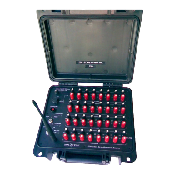
Page 4: Receiver Hardware Description
This manual is divided into six sections. The first is a description of the receiver hardware. The second is a description of the transmitter hardware. The third describes possible effects of radio interference and design techniques used to prevent it. The fourth describes operation of the system in rapid-fire (burst) mode. - Page 5 All received commands are contained in transmitted data packets which are digitally decoded and executed. These packets contain extensive error detection coding and are transmitted reduntantly multiple times on multiple frequencies to enhance successful communication even in the presence of severe narrow band interference. All communication is “two way”...
-
Page 6: The Antenna
A detailed description of the receiver components follows: THE ANTENNA. The RF signal is received and transmitted through a half-wave dipole antenna. This antenna must be folded down in order to close the receiver box. The receiver may be operated in the folded configuration, but maximum range will be achieved when the antenna is unfolded and vertical. -
Page 7: The Fire Signal Indicator
THE FIRE SIGNAL INDICATOR. This red indicator lights whenever a valid FIRE signal is received from the radio channel or from the MANUAL FIRE button. THE FIRE OUTPUT INDICATOR. This indicator lights red whenever firing voltage is present on the output terminals. -
Page 8: The Output Connectors
THE OUTPUT CONNECTORS. Electric matches or other devices to be actuated are connected to spring terminals (pyro-clips) on the receiver panel or optionally to an external firing strip connector on the rear of the receiver box. The panel contains 32 red and black terminal pairs for connection to the devices to be actuated by receiver cues 1 –... -
Page 9: The Charger Connector
THE CHARGER CONNECTOR. This connector is used to attach the battery charger. The battery charger can charge a fully discharged battery in about 4 hours, after which it switches automatically from high rate mode to trickle charge mode. It can be left connected indefinitely in this mode. -
Page 10: 1.10 Optional Firing Connector Pinout
1.10 OPTIONAL FIRING CONNECTOR PINOUT. Connector description: 50 position SCSI-I .085" female panel receptacle. Digi-key part number: 1050F-ND Mating connector: 50 position male Centronics cable connector with boot Digi-key part number: T1504-ND Pin # Description Notes Output (connects to negative side of 12 volt source while firing) Output (connects to negative side of 12 volt source while firing) Output... -
Page 11: Transmitter Hardware Description
TRANSMITTER HARDWARE DESCRIPTION. Rcvr Signal Indicator Battery Indicator Fire Button Test Button Numeric Indicators Mode / Program Button Power / Clear Button Arm Button Page 11 of 24... - Page 12 The model 10000TS “Spread Spectrum” Two Way Firing Transmitter is a long range frequency-hopping spread spectrum two radio transceiver designed to be used for remote control applications where high reliability is critical. When used with Holatron model 10000RS “Spread Spectrum” two way receivers, a range of two miles (line of sight operation) is typical, provided there are no intervening conductive objects such as automobiles, chainlink fences, etc.
-
Page 13: The Antenna
A detailed description of the transmitter components follows: THE ANTENNA. Radio commands are transmitted and responses received through a half-wave dipole antenna. This antenna is permanently attached to the transmitter box. Range will be greatest when the transmitter is oriented so that the antenna is parallel to the receiver antennas, normally a vertical orientation. -
Page 14: The "Receiver Signal" Indicator
THE “RECEIVER SIGNAL” INDICATOR. The strength of the transmitted beacon at the receiver selected by the “Next Cue” number is indicated by the flashing of this lamp. It flashes intermittently in bursts of two, three, or four flashes at a time if the beacon is being received by the receiver. -
Page 15: The "Next Cue" Entry Buttons
THE “NEXT CUE” ENTRY BUTTONS. The number of the next cue to be fired or tested is entered on the ten numerical buttons, with 9999 being the highest number that can be entered. Entered dIgits are appended to the right side of the number being displayed (like a calculator). A new number can be entered (erasing the currently displayed number) after one of the five non-numerical function buttons has been pressed. -
Page 16: The Fire Button
This selection-fire sequence can be repeated as required. Note that this is a manual firing system, and it is not currently configured to fire programmed sequences. Holatron Systems offers optional transmitter accessory modules with preprogrammed firing modes such as “automatic fire”... -
Page 17: 2.11 The Mode / Program Button
2.11 THE MODE / PROGRAM BUTTON. This button, labeled Prgm Rcvr, sequentially selects one of three programming modes or the normal operating mode. In the normal operating mode, the Bat / Rcvr Program indicator flashes green to indicate the transmitter battery status, as described in section 2.3 above. - Page 18 While in # OF RECEIVER CUES mode, entering a cue number followed by depression of the Prgm Rcvr button will cause that number to be programmed as the total number of cues to be fired by the receiver being programmed. This number should not normally be set higher than the total number of outputs available in the receiver being programmed (usually 32, 45 or 48).
-
Page 19: Radio Interference Reduction
RADIO INTERFERENCE REDUCTION. For obvious safety reasons, Holatron's design goal is to ensure that data communication errors due to radio interference or to insufficient signal strength due to low battery, exceeding specified range, or conductive objects in the signal path will result in failure of intentional actuation rather than unintended actuation. -
Page 20: Rapid-Fire Burst Mode
RAPID-FIRE BURST MODE. This transmitter incorporates built-in rapid-fire burst capability which is accessed by pressing the mode button while the transmitter is armed. When in rapid-fire mode, the “Bat / Selected Mode” indicator turns red and flashes continually at the selected rapid- fire rate. - Page 21 Transmitter Firing Mode State Diagram Semi-automatic Power mode, Prgrm Rcvr button disarmed button Numeral keys Display Enter new cue # next cue # & display Numeral Numeral keys buttons Semi-automatic mode, Semi-automatic mode, Fire displayed cue # FIRE button button disarmed armed &...
-
Page 22: Specifications
SPECIFICATIONS. Parameter Minimum Typical Maximum Spread Spectrum Carrier Frequency-hopping 902.217 927.492 Range, MHz. (US & Canada) Spread Spectrum Carrier Frequency-hopping 927.492 Range, MHz. (Australia) Range 5 feet 2 miles (line-of-sight, no intervening conductive objects) Transmit Signal Security Code Length 80 bits Transmit Retries per Command Failure Radio Communications Link Data Rate 76.8... -
Page 23: Operation And Maintenance
OPERATION AND MAINTENANCE. This section describes the recommended operating procedure and maintenance for the transmitter-receiver system. OPERATION. Note that the transmitter and receiver should be separated by at least 5 feet to establish a radio link. Smaller separations overload the receiver input circuitry, corrupting communication. -
Page 24: Maintenance
NOT water tight. The transmitter and receiver must never be immersed in water. If further information or service is required, contact: Holatron Systems, LLC. 2800 Woodlawn Dr., Suite 138 Honolulu, HI 96822 (808) 372-0956 www.holatron.com...
Need help?
Do you have a question about the SPREAD SPECTRUM 12V and is the answer not in the manual?
Questions and answers