
Summary of Contents for HOLATRON SYSTEMS SureFire-1
- Page 1 OPERATION & MAINTENANCE GUIDE - SureFire-1 High Energy Trigger HOLATRON SYSTEMS, LLC Honolulu, HI , USA www.holatron.com...
- Page 2 Holatron Systems, LLC, from same, whether brought by the user, user’s agent, or assigns, or any third party.
-
Page 3: Hardware Description
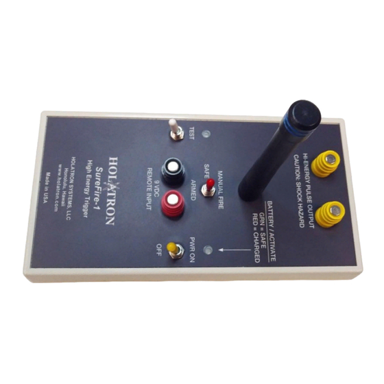
This manual is divided into five sections. The first is a description of the system hardware. The second details techniques to minimize radio interference, the third lists system specifications, the fourth describes operating procedure, and the fifth describes recommended maintenance. HARDWARE DESCRIPTION. - Page 4 The user has access to the following components (refer to figures 1 & 2): THE ANTENNA. The RF signal is received by a quarter wave antenna which screws onto the top of the module. The antenna should be removed for storage. The antenna need not be tight to achieve a good electrical connection.
- Page 5 The MANUAL FIRE position is a momentary spring return position which, if not in “radio-only” mode, causes the output to fire when actuated within 3 seconds of having been in ARMED position. Switching to SAFE for more than 3 seconds disables the MANUAL FIRE function until the switch is again placed in ARMED position.
-
Page 6: The Test Indicator
THE TEST INDICATOR. This indicator, located just above the TEST switch, lights green when the switch is momentarily pressed upward if there is a device connected between the yellow output terminals. This test uses a one milliampere current to perform a galvanometer function that verifies continuity through the device connected to the output, ensuring that a successful firing will occur when the module is actuated. - Page 7 THE BATTERIES. All power is supplied from four AA alkaline batteries, contained in a compartment in the bottom of the plastic box as shown below: Digital Switch Access Hole The batteries should be replaced when required by conditions described in section 1.3 above.
- Page 8 The digital switch has been initially set to position “5” at the factory for operation by radio, wire-fire, and manual-fire, with energy level of 12.3 joules (316 VDC output pulse). Access to this switch is gained by removing the adhesive seal over the hole in the bottom cover shown in section 1.7 above.
- Page 9 RADIO INTERFERENCE REDUCTION. For obvious safety reasons, Holatron's design goal is to ensure that data communication errors due to radio interference or to insufficient signal strength due to low battery, exceeding specified range, or conductive objects in the signal path will result in failure of intentional actuation rather than unintended actuation.
-
Page 10: Specifications
SPECIFICATIONS. Parameter Minimum Typical Maximum Carrier Frequency, MHz. 417.96 418.02 418.08 Range ½ mile (line-of-sight with XMTR12B or RFLS-1XT xmtr) Delay from start of transmission to fire output 100 msec Charge-up time from pwr-on to max energy level 9 sec Average battery drain, (1.14 joules) 20 mA Average battery drain, (12.3 joules) - Page 11 Contact Holatron Systems first. 4.1.6 If firing by radio, move to a safe distance and wait until you are ready to fire before turning on the transmitter.
-
Page 12: Pairing With A Transmitter
4.1.10 Alternatively, if not in “radio only” mode, you can fire manually or by wire by applying a contact closure or 9 VDC signal to the remote input terminals. Red is positive, and black is negative. The remote input terminals are optically isolated from the high voltage output for safety. If not in “radio-only”... -
Page 13: Maintenance
For prolonged storage or shipping, the batteries should be removed. The antenna can also be removed by unscrewing it. If further information or service is required, contact: Holatron Systems, LLC. 2800 Woodlawn Dr., Ste. 138 Honolulu, HI 96822-1864 808-372-0956 www.holatron.com...
Need help?
Do you have a question about the SureFire-1 and is the answer not in the manual?
Questions and answers