Advertisement
Quick Links
RED Status LED FLASHING (Automatic battery
and radio strength test)
The auto-test routine is very important. The
Roboguard sends an 'auto-test' radio signal to the
keypad every 20 minutes. Should a guard fail to
report in, the AI will indicate this by flashing the
red status LED. To establish which Roboguard is
reporting the status condition and to reset the
status LED you must do the following.
NOTE: Status indicates potential
communication problems that may be due to
bad radio reception, battery problems or faulty
TX or CPU PIRs.
1. Press and release the status button (Status
LED "ON", AI is now in Status condition
display mode)
2. The zone LED for the Roboguard that has
reported Status will be on guard.
3. Press and release all ON LED's so only the
red Status LED is "ON".
4. Press and release the Status button (LED off)
or do nothing as the keypad will time out and
exit automatically.
5. Determine what is causing the Roboguard to
fail auto-test and correct the problem.
THIS 24HR ZONE IS THE HEART BEAT
OF THE PROGRAMMED GUARDS AND
WILL REMAIN OPEN CIRCUIT, UNTIL
THE PROBLEM HAS BEEN SOLVED.
INSTALLERS DETAILS
Name:
Company:
Contact details:
Cell:
Date of installation:
NOTES
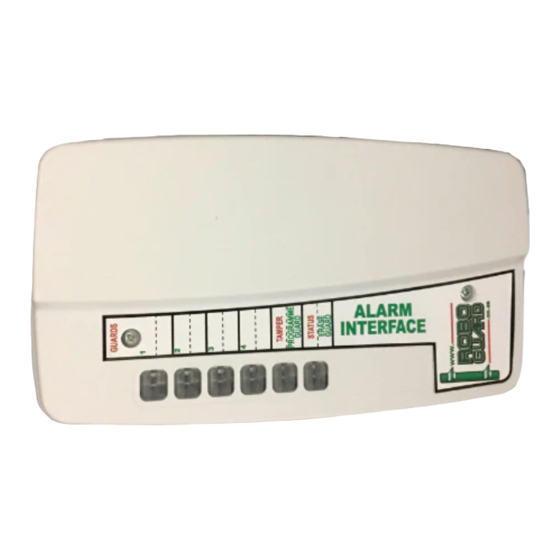
Alarm Interface Manual
Specifications:
Dimensions: 170 x 95 x 29 mm
Weight: 180 gsm
Current Consumption: 10 m A
Required Power Supply: +12V D.C.
• The Alarm Interface(AI)can, supervise and monitor
up to four Roboguards, with individual intruder
detected, tamper and status LED's.
• The Alarm Interface has six relay switches all
N/O and N/C
ISO 9000-2000 Approved
Advertisement

Summary of Contents for RoboGuard Alarm Interface
- Page 1 WILL REMAIN OPEN CIRCUIT, UNTIL • The Alarm Interface(AI)can, supervise and monitor THE PROBLEM HAS BEEN SOLVED. up to four Roboguards, with individual intruder detected, tamper and status LED’s. • The Alarm Interface has six relay switches all N/O and N/C ISO 9000-2000 Approved...
- Page 2 (C) General Operation trigger and correct the problem. the Roboguard. If the Alarm interface is not The Alarm Interface is used to interface up to four yet connected to the alarm panel, you can Roboguards. see the trigger, as the guard light will start...
Need help?
Do you have a question about the Alarm Interface and is the answer not in the manual?
Questions and answers