Advertisement
Quick Links
PREFACE
Thank you for purchasing the Navis anemometer. This manual provides information for the best performance and safe application of
the anemometer display unit. This manual does not cover the anemometer sensors for which the manuals will come separately.
Read this manual carefully before starting the installation. Keep this manual after installation for future reference.
INTRODUCTION
W410 models are long-range display units which receive data from NAVIS wind sensors, display various wind data and use internal
and external alarms for warnings about excess wind speed. Smartphone compatibility (W410XB/D, W410XL/D models) allows real-time
wind data monitoring on smartphones or tablets. Wi-Fi compatibility (W410XW/D, W410XL/D models) allows real-time wind data
monitoring on "Navis Live Data" web interface. 4-20 mA output (W410XB/D, W410XW/D and W410XL/D models) allows connection to
external devices. Various wind data can be stored on SD card (W410XL/D model).
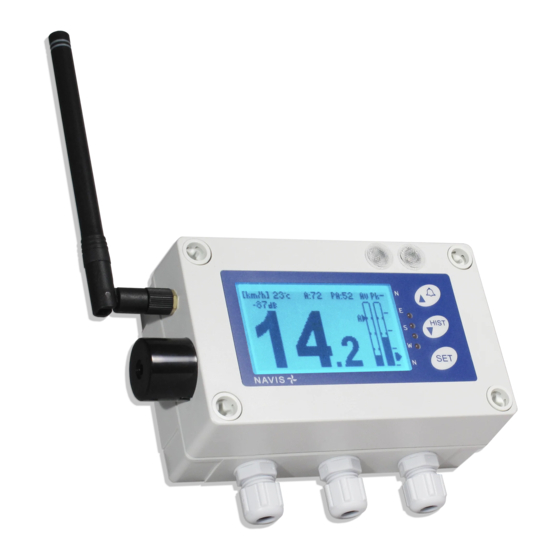
Figure 1. (W410 display unit – front panel)
The W410 display is compatible with NAVIS sensors: WS 010-1 (wind speed sensor, standard range), WS 011-1 (wind speed sensor,
extended range), WSD 010-1 (wind speed/direction sensor, standard range), WSD 011-1 (wind speed/direction sensor, extended
range), WS 011-1-EX (wind speed sensor for explosive environments), WSD 011-1-EX (wind speed/direction sensor for explosive
environments).
MOUNTING
Select the position where the signal reception is strong enough under all conditions. Use remote antenna if necessary.
Display unit can be mounted onto the ferrous surface with four mounting magnets (optional accessories) or with mounting screws (not
enclosed) to any flat surface.
Mounting the display unit with screws:
Unscrew all 4 plastic screws and remove the front panel. Note that the screws can be pulled out only at the correct angle. Place the
rear panel of the display unit to the final mounting position and mark the position for the bores. Remove the casing and drill holes for
the mounting screws. Place the rear panel of the display unit in position and tighten the mounting screws. Attach the front panel of the
display unit with 4 plastic screws.
ANTENNA CONNECTION
Connect the enclosed antenna to the SMA connector on the display unit only when the power supply is switched OFF.
OPERATION
If the display unit is delivered as a set, with the sensor included, the correct sensor address is already set.
Otherwise please set the correspondent sensor address first. Check the address settings procedure in the chapter "SETTINGS".
Turn the sensor ON by rotating the sensor cups (see sensor user manual).
Fresh wind data are received every two seconds. If data are not received for more than 30 seconds, the "No data" notification appears
on the display.
W410 DISPLAY UNIT
MANUAL
Models: W410/D, W410XB/D, W410XW/D, W410XL/D
1. Display
2. Red and Yellow alarm lights
3. Keys
4. Relays signal lights
5. Buzzer
6. SMA antenna connector
7. SD card insertion
Advertisement

Related Manuals for NAVIS W410 Series


Summary of Contents for NAVIS W410 Series
- Page 1 Read this manual carefully before starting the installation. Keep this manual after installation for future reference. INTRODUCTION W410 models are long-range display units which receive data from NAVIS wind sensors, display various wind data and use internal and external alarms for warnings about excess wind speed. Smartphone compatibility (W410XB/D, W410XL/D models) allows real-time wind data monitoring on smartphones or tablets.
- Page 2 WIRING Please note! Switch off the power before connecting the power supply to the display unit. Unscrew all 4 plastic screws and remove the front panel. Connect the 12-24 V DC power supply. For using external alarm devices, connect them to the relay connection terminals. For using 4-20mA outputs (only at W410XB/D, W410XW/D and W410XL/D models), connect the connection terminals to external devices.
-
Page 3: Troubleshooting
When display unit receive data from wind sensor, data packet is transmitted through Wi-Fi connection to “Navis Live Data” web interface. On Navis “Live Data” web interface it can be observed data of current, average and maximum wind speed, wind direction, temperature or view history graphs. - Page 4 Example of logged first 10 wind data from WSD sensor in 10s logging interval. Average [WS] and maximum [WSm] wind speed data are in units of m/s, temperature in degrees of Celsius [WSt], wind direction [WD] in degrees and signal strength [RSSI] in dB. <------Navis Elektronika W410 v010119-------> <------------------------------------------->...
- Page 5 SETTINGS: SETTINGS PROCEDURE 1. Hold down the SET key to enter the settings menu. If password protection is active, enter the correct password. The group of settings displays on the display. 2. Select the group by using the up and down keys and press the SET key to view the selected group. 3.
-
Page 6: Technical Data
WARRANTY (LIMITED) The warranty period of NAVIS products is one year after the date of purchase. During the limited warranty period any defective product will be repaired or replaced with a comparable product without charges. The claimed product will be repaired or replaced only when returned to the store where it was purchased together with original invoice.