
Summary of Contents for Schaltbau C195 Series
- Page 1 Contactors C195 series Single pole compact universal NO and CO contactors Installation and maintenance instructions Manual B195-M.en...
-
Page 2: Table Of Contents
Electrical hazards ......................... 6 Other hazards ........................6 Measures for avoiding damage and malfunctions ..........7 Product information ......................8 C195 Series – Single pole NO and changeover contactors plus bidirectional variants ....................8 Features ........................... 8 Applications ........................... 8 Technical information and material properties ............ - Page 3 8.4.6 Replacing the contact bridge unit – type C195 A/, B/, S/, T/, W/ .......57 8.4.7 Replacing the main contacts – type C195 A/, B/, S/, T/, W/ .........58 Spare parts ........................60 10. Technical data .........................61 11. Disposal ...........................61 Contactors C195 Series – Installation and Maintenance Instructions 2021-02-10 / V1.0...
-
Page 4: Important Basic Information
Always adhere strictly to all safety instructions! Only authorised and trained personnel are allowed to plan and carry out all mechanical and electrical instal- Contactors C195 Series – Installation and Maintenance Instructions 2021-02-10 / V1.0... -
Page 5: Duties Of The Operating Company
The catalogue is https://www.schaltbau.com/en/media-library/ available under: https://www.schaltbau.com/en/media-library/ The contactors may only be used when all protec- tive devices are present, have been correctly in- stalled and are fully operational. Contactors C195 Series – Installation and Maintenance Instructions 2021-02-10 / V1.0... -
Page 6: Hazards And Safety Precautions
CAUTION The contactors contain sharp-edged parts. Risk of injuries! Use appropriate tools for installation and maintenance work on the contactors. Wear safety gloves when handling sharp-edged components. Contactors C195 Series – Installation and Maintenance Instructions 2021-02-10 / V1.0... -
Page 7: Measures For Avoiding Damage And Malfunctions
Record the frequency of undoing of the screws in the work log. Replace detent-edged rings or detent-edged washers with new ones after the screws have been undone three times. Contactors C195 Series – Installation and Maintenance Instructions 2021-02-10 / V1.0... -
Page 8: Product Information
Being of compact size and featuring double-break con- works – or in combination with a precharging con- tacts that are covered for the most part, the C195 Series tactor for a host of applications in trains, multiple contactors provide highperformance current breaking. -
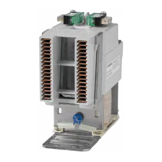
Page 9: Overview (Stock Items)
Fastening holes for M8 screws Earthing connection M5, torque: 2.4-3 Nm Coil terminals A1 and A2, flat plug connections 6.3 x 0.8 mm Coil suppression: Varistor Main contacts, connection M8, torque: 8-10 Nm Contactors C195 Series – Installation and Maintenance Instructions 2021-02-10 / V1.0... - Page 10 Permanent magnet (inside the housing) Fastening holes for M6 screws Coil terminals A1 and A2, flat plug connections 6.3 x 0.8 mm Coil suppression: Varistor Main contacts, connection M8, torque: 9.5-12 Nm Contactors C195 Series – Installation and Maintenance Instructions 2021-02-10 / V1.0...
- Page 11 Fastening holes for M6 screws Coil terminals A1 and A2, flat plug connections 6.3 x 0.8 mm Main contacts, connection M8, torque: 9.5-12 Nm Auxiliary switch (1x S870 W1B1 a 065) for board switching (hard-wired) Contactors C195 Series – Installation and Maintenance Instructions 2021-02-10 / V1.0...
- Page 12 Auxiliary switches (2x S870), flat plug connections 6.3 x 0.8 mm Arch chamber Plasma-exits Fastening holes for M6 screws Coil terminals A1 and A2, flat plug connections 6.3 x 0.8 mm Coil suppression: Varistor Main contacts, connection M8, torque: 9.5-12 Nm Contactors C195 Series – Installation and Maintenance Instructions 2021-02-10 / V1.0...
- Page 13 Permanent magnets (inside the housing) Fastening holes for M6 screws Coil terminals A1 and A2, flat plug connections 6.3 x 0.8 mm Coil suppression: Varistor Main contacts, connection M8, torque: 9.5-12 Nm Contactors C195 Series – Installation and Maintenance Instructions 2021-02-10 / V1.0...
- Page 14 Fastening holes for M6 screws Coil terminals A1 and A2, flat plug connections 6.3 x 0.8 mm Main contacts, connection M8, torque: 9.5-12 Nm Auxiliary switch (1x S870 W1B1 a 065) for board switching (hard-wired) Contactors C195 Series – Installation and Maintenance Instructions 2021-02-10 / V1.0...
- Page 15 Auxiliary switches (2x S870): flat plug connections 6.3 x 0.8 mm Plasma-exits Fastening holes for M6 screws Coil terminals A1 and A2, flat plug connections 6.3 x 0.8 mm Coil suppression: Varistor Main contacts, connection M8, torque: 9.5-12 Nm Contactors C195 Series – Installation and Maintenance Instructions 2021-02-10 / V1.0...
- Page 16 Coil terminals A1 and A2, flat plug connections 6.3 x 0.8 mm Coil suppression: Varistor Main contacts NO (normally opened), connection M8, torque: 9.5-12 Nm Main contacts NC (normally closed), connection M8, torque: 4.8-6 Nm Contactors C195 Series – Installation and Maintenance Instructions 2021-02-10 / V1.0...
-
Page 17: Storage
6.2 Check parts for transport damage ATTENTION If parts are damaged, functional reliability of the con- tactor has been lost. Before installing, check all parts for possible transport damage. Do not install damaged parts. Contactors C195 Series – Installation and Maintenance Instructions 2021-02-10 / V1.0... -
Page 18: Installation
“7.1.8 Installing the contactor” on page 20. The length of the mounting screws must be deter- mined dependent on the structural circumstances. Contactors C195 Series – Installation and Maintenance Instructions 2021-02-10 / V1.0... -
Page 19: Mounting Positions
±90° 7.1.7 Tools required Fig. 13: Examples of non-permissible mounting positions - Socket spanner set, hexagon nuts, set of hexagon socket spanners - Torque spanner Contactors C195 Series – Installation and Maintenance Instructions 2021-02-10 / V1.0... -
Page 20: Installing The Contactor
C195 S/) Fig. 14: C195 X/: Installing the contactor on the mounting plate or frame Fig. 17: C195 W/: Installing the contactor on the mounting plate or frame Contactors C195 Series – Installation and Maintenance Instructions 2021-02-10 / V1.0... -
Page 21: Electrical Connection
(6.3 x 0.8 mm). The maximum permissible conductor cross-section of the auxiliary switch control wires is 1 mm / AWG 18 stranded wire. Contactors C195 Series – Installation and Maintenance Instructions 2021-02-10 / V1.0... -
Page 22: Safety
Replace detent-edged rings or detent-edged washers with new ones after the screws have been undone three times. 7.2.4 Tools required - Socket spanner set, hexagon nuts - Open-ended spanner set - Torque spanner - Continuity tester - Cable ties Contactors C195 Series – Installation and Maintenance Instructions 2021-02-10 / V1.0... -
Page 23: Connecting The Auxiliary Switches
Fig. 20: C195 S/, C195 T/: Connecting the S870 auxiliary switches (the figure shows C195 S/, the procedure is identical for C195 T/) Fig. 18: C195 X/: Connecting the S870 auxiliary switches Contactors C195 Series – Installation and Maintenance Instructions 2021-02-10 / V1.0... -
Page 24: Auxiliary Switches At Latching Contactor Variants
6.3 x 0.8 mm Fig. 22: C195 S/ ...BD, latching contactor: Connecting the S870 auxiliary switch Fig. 21: C195 A/ ...BD latching contactor: Connecting the S870 auxiliary switch Contactors C195 Series – Installation and Maintenance Instructions 2021-02-10 / V1.0... -
Page 25: Connecting The Coil
6.3 x 0.8 mm Fig. 25: C195 S/, C195 T/: Connecting the coil (the figure shows C195 S/, the procedure is identical for C195 T/) Fig. 23: C195 X/: Connecting the coil Contactors C195 Series – Installation and Maintenance Instructions 2021-02-10 / V1.0... -
Page 26: Coil Connections At Latching Contactor Variants
(4) to the coil terminals A1, A2 and A3 (5). If applicable bundle and secure the wires using Fig. 28: C195 S/ ...BD latching contactor: Connecting the coil cable ties. Contactors C195 Series – Installation and Maintenance Instructions 2021-02-10 / V1.0... -
Page 27: Connecting The Main Contacts
Fig. 30: C195 A/, C195 B/: Connecting the main contacts: Ex- ample of a connection with cables (the figure shows C195 A, the procedure is identical for C195 B/) Contactors C195 Series – Installation and Maintenance Instructions 2021-02-10 / V1.0... - Page 28 (1). Screw the ring terminals (2) to the lower main con- tacts (1) using the terminal screws (4) and washers (5). - Schaltbau recommends using Schnorr washers (or similar). Contactors C195 Series – Installation and Maintenance Instructions 2021-02-10 / V1.0...
-
Page 29: Main Contact Connection With Busbars
Fig. 34: C195 A/, C195 B/: Connecting the main contacts: 9.5-12 Nm (NO contacts) Example of a connection with busbars (7) and angled C195 W/ connecting bars (8) 4.8-6 Nm (NC contacts) Contactors C195 Series – Installation and Maintenance Instructions 2021-02-10 / V1.0... - Page 30 (6) or compensating angled connecting bars if necessary. Fig. 37: C195 W/: Connecting the main contacts: Example of a connection with busbars (7) and connecting bars (6) to NO and NC contacts Contactors C195 Series – Installation and Maintenance Instructions 2021-02-10 / V1.0...
-
Page 31: Connecting The Earth Terminal (Only For C195 X/)
- EN/IEC 60077-2 - EN/IEC 60947-4-1 2.4-3 Nm Fig. 38: Connecting the earth terminal (only for C195 X/) Contactors C195 Series – Installation and Maintenance Instructions 2021-02-10 / V1.0... -
Page 32: Maintenance
External visual inspection of the con- 1x per year tactor Immediately submit any damaged contactors or components for Check of the main contacts Every 3 years maintenance. Check of the auxiliary switches Every 3 years Contactors C195 Series – Installation and Maintenance Instructions 2021-02-10 / V1.0... -
Page 33: Regular Tests/Checks
Under normal working condition (there have been no short circuits in the control circuit) the life time of the auxiliary switches exceeds those of the contactor. Contactors C195 Series – Installation and Maintenance Instructions 2021-02-10 / V1.0... - Page 34 (minimum coating: 0.3 mm, unit – type C195 X/” in new condition: 1.2 mm). or “8.4.3 Replacing the complete con- tact unit – type C195 A/, B/, S/, T/, W/” Contactors C195 Series – Installation and Maintenance Instructions 2021-02-10 / V1.0...
-
Page 35: Corrective Maintenance Measures - Type C195 X
- Disassembling the armature - Removing the cover - Disassembling the connecting plate To replace the main contacts, the contact bridge unit must additionally be disassembled. Contactors C195 Series – Installation and Maintenance Instructions 2021-02-10 / V1.0... -
Page 36: Removing/Inserting The Pole Plates - Type C195 X
Unscrew the 2 screws (1) on the cover (7) of the contactor. Carefully lift the contact unit (2) off the magnetic drive (3). Contactors C195 Series – Installation and Maintenance Instructions 2021-02-10 / V1.0... -
Page 37: Disassembling/Assembling The Armature - Typ C195 X
– type C195 X/” on page 36. Disassembly Pull the armature (4) at the bottom of the contact unit and unhook the armature (4) laterally from the contact bridge unit (5). Contactors C195 Series – Installation and Maintenance Instructions 2021-02-10 / V1.0... -
Page 38: Removing/Attaching The Cover - Type C195 X
Grasp the auxiliary switch actuator (6) and hold it ing the cover – type C195 X/” on page 38. firmly so that the position of the connection plate (12) can no longer change. Contactors C195 Series – Installation and Maintenance Instructions 2021-02-10 / V1.0... -
Page 39: Disassembling/Assembling The Contact Bridge Unit - Type C195 X
- The cover is removed, see section “Removing/at- taching the cover – type C195 X/” on page 38. - The connecting plate is removed, see section “Dis- assembling/assembling the connecting plate – type C195 X/” on page 38. Contactors C195 Series – Installation and Maintenance Instructions 2021-02-10 / V1.0... -
Page 40: Replacing The Auxiliary Switches - Type C195 X
Tighten the new self-tapping screws (1) to a torque of 0.65-0.8 Nm. Connect the control wires to the new auxiliary switches (2), see section “7.2 Electrical connec- tion”/ “7.2.5 Connecting the auxiliary switches” on page 23. Contactors C195 Series – Installation and Maintenance Instructions 2021-02-10 / V1.0... -
Page 41: Replacing The Complete Contact Unit - Type C195 X
Before disassembling, note the orientation of the old contact unit in relation to the base plate. Disassemble the contact unit, see section “Disas- sembling/assembling the contact unit – type C195 X/” on page 36. Contactors C195 Series – Installation and Maintenance Instructions 2021-02-10 / V1.0... -
Page 42: Replacing The Magnetic Drive - Type C195 X
Remove the cover, see section “Removing/attach- ing the cover – type C195 X/” on page 38. Disassemble the connecting plate, see section “Disassembling/assembling the connecting plate – type C195 X/” on page 38. Contactors C195 Series – Installation and Maintenance Instructions 2021-02-10 / V1.0... -
Page 43: Replacing The Contact Bridge Unit - Type C195 X
– Typ C195 X/” on page 37. sembling/assembling the pole packs – Typ C195 Disassemble the contact bridge unit, see section X/” on page 35. „Disassembling/assembling the contact bridge unit – type C195 X/“. Contactors C195 Series – Installation and Maintenance Instructions 2021-02-10 / V1.0... -
Page 44: Replacing The Main Contacts - Type C195 X
Finally, subject the contactor to a complete check as described in section “7.4 Checks” on page 31. Remove the two main contacts (17) upwards from the contact unit (2). Contactors C195 Series – Installation and Maintenance Instructions 2021-02-10 / V1.0... - Page 45 Insert the 2 pole plates. See section “Removing/ inserting the pole plates – type C195 X/” on page Assemble the 2 pole packs. See section “Disassem- bling/assembling the pole packs – Typ C195 X/” on page 35. Contactors C195 Series – Installation and Maintenance Instructions 2021-02-10 / V1.0...
-
Page 46: Corrective Maintenance Measures - Type C195 A/, B/, S/, T/, W
Fig. 54: C195 A/, C195 B/: Disassembling/assembling the con- - Disassembling the connecting plate tact unit (the figure shows C195 A/, the procedure is - Disassembling the contact bridge unit identical for C195 B/) Contactors C195 Series – Installation and Maintenance Instructions 2021-02-10 / V1.0... - Page 47 Fig. 55: C195 S/, C195 T/: Disassembling/assembling the con- tact unit (the figure shows C195 S/, the procedure is identical for C195 T/) 0.8-1 Nm Fig. 56: C195 W/: Disassembling/assembling the contact unit Contactors C195 Series – Installation and Maintenance Instructions 2021-02-10 / V1.0...
-
Page 48: Disassembling/Assembling The Armature - Type C195 A/, B/, S/, T/, W
(the figure shows C195 S/, the procedure is identical for C195 T/) Fig. 61: C195 S/, C195 T/: Assembling the armature (the figure shows C195 S/, the procedure is identical Fig. 59: C195 W/: Disassembling the armature for C195 T/) Contactors C195 Series – Installation and Maintenance Instructions 2021-02-10 / V1.0... - Page 49 Maintenance Fig. 62: C195 W/: Assembling the armature Contactors C195 Series – Installation and Maintenance Instructions 2021-02-10 / V1.0...
-
Page 50: Removing/Attaching The Cover - Type C195 A/, B/, S/, T/, W
Place the cover (7) on the contact unit (2). Screw in the 2 screws (1) on the cover (7) of the con- tactor and tighten them with a torque of 0.8-1 Nm. Contactors C195 Series – Installation and Maintenance Instructions 2021-02-10 / V1.0... -
Page 51: Disassembling/Assembling The Contact Bridge Unit - Type C195 A/, B/, S/, T/, W
(2). Make sure that - the sealing ring (13) and the contact pressure spring (14) are in place and correctly positioned, - the return spring (15) is in place and correctly positioned. Contactors C195 Series – Installation and Maintenance Instructions 2021-02-10 / V1.0... -
Page 52: Replacing The Auxiliary Switches - Type C195 A/, B/, S/, T
Remove the auxiliary switches (2) from the contac- tor top. Fig. 70: C195 S/, C195 T/: Replacing the auxiliary switches (the figure shows C195 S/, the procedure is identical for C195 T/) Contactors C195 Series – Installation and Maintenance Instructions 2021-02-10 / V1.0... -
Page 53: Auxiliary Switches For Latching Contactor Types
S/, T/” on page 52, but only the customer usable auxiliary switch (2) is replaced instead of 2 auxil- iary switches. Fig. 72: C195 S/ ...BD, latching version: replace the single auxiliary switch S870 (2) Contactors C195 Series – Installation and Maintenance Instructions 2021-02-10 / V1.0... -
Page 54: Replacing The Complete Contact Unit - Type C195 A/, B/, S/, T/, W
Disassemble the contact unit, see section “Dis- assembling/assembling the contact unit – type C195 A/, B/, S/, T/, W/” on page 46. Contactors C195 Series – Installation and Maintenance Instructions 2021-02-10 / V1.0... -
Page 55: Replacing The Magnetic Drive - Type C195 A/, B/, S/, T/, W
Before installing the contact unit on the mag- netic drive, observe the previously noted cor- rect orientation in relation to the base plate. Contactors C195 Series – Installation and Maintenance Instructions 2021-02-10 / V1.0... -
Page 56: Replacing The Arcing Chamber - Type C195 A/ Und C195 B
Hold the lower part of the contact unit (2) and pull out the arcing chamber (13) upwards. Fig. 73: C195 A/, C195 B/: Removing/attaching the arcing chamber (the figure shows C195 A/, the procedure is identical for C195 B/) Contactors C195 Series – Installation and Maintenance Instructions 2021-02-10 / V1.0... -
Page 57: Replacing The Contact Bridge Unit - Type C195 A/, B/, S/, T/, W
– type C195 A/, B/, S/, T/, W/” on page Disassemble the contact bridge unit, see section “Disassembling/assembling the contact bridge unit – type C195 A/, B/, S/, T/, W/” on page 51. Contactors C195 Series – Installation and Maintenance Instructions 2021-02-10 / V1.0... -
Page 58: Replacing The Main Contacts - Type C195 A/, B/, S/, T/, W
Remove the two main contacts (17) upwards from the contact unit (2). Fig. 75: C195 S/, C195 T/: Replacing the main contacts (the figure shows C195 S/, the procedure is identical for C195 B/) Contactors C195 Series – Installation and Maintenance Instructions 2021-02-10 / V1.0... - Page 59 “7.2 Electrical connection” on page 21. Finally, subject the contactor to a complete check as described in section “7.4 Checks” on page 31. Fig. 77: C195 W/: Replacing the upper main contacts (NC contacts) Contactors C195 Series – Installation and Maintenance Instructions 2021-02-10 / V1.0...
-
Page 60: Spare Parts
Magnetic armature Moving component (contact Contact bridge unit bridge, contact pressure spring, contact carrier and sealing ring) Main contacts Main contacts (2 pieces) Main contacts NC NC contacts (2 pieces) Contactors C195 Series – Installation and Maintenance Instructions 2021-02-10 / V1.0... -
Page 61: Technical Data
Technical data 10. Technical data Technical data and information on the material proper- ties for the contactors of the C195 series are given in our B195 catalogue. Schaltbau products are subject to continual improve- ment. Therefore, the product information in catalogues, data sheets, etc. - Page 62 Notes Notes Contactors C195 Series – Installation and Maintenance Instructions 2021-02-10 / V1.0...
- Page 63 Notes Contactors C195 Series – Installation and Maintenance Instructions 2021-02-10 / V1.0...
- Page 64 High-voltage heaters ■ High-voltage roof equipment ■ Equipment for electric brakes ■ Design and engineering of train electrics to customer requirements We reserve the right to make technical alterations without prior notice. Printed in Germany For updated product information visit www.schaltbau-gmbh.com..
Need help?
Do you have a question about the C195 Series and is the answer not in the manual?
Questions and answers