Table of Contents
Advertisement
Quick Links
Overview
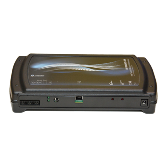
DI-1000UHS-10K High Speed USB Load Cell Interface is used to
capture dynamic force information at high sampling rates up to 50
KHz. Examples of such applications include failure strength testing,
impact force measurements, vibration testing and material
characterization. It can be used with any resistive load cell.
Features
Data capture up to 50 kHz sample rates over USB, 1 kHz if you use it over Bluetooth. Note:
§
Loadstar sensors does not currently provide software to operate the unit over Bluetooth mode.
USB data acquisition
§
Plug and play operation with LV-1000HS-10K software and factory calibrated load cells.
§
Select data acquisition rate from 1KHz to 50Khz
§
True force measurement (not just G-values)
§
Analog calibration feature for easy calibration of your load cell.
§
Package Contents
DI-1000UHS-10K High Speed USB Load Cell Interface
§
Power supply (12 V). The unit will accept between 9 to 24 V.
§
USB Cable to connect to the computer (typically 6 foot long)
§
Resistive load cell with capacity option of up to 100,000 pounds.
§
Since impact loads can be extremely large depending on duration of contact of impacting objects,
§
object drop heights, coefficients of rigidity etc. care must be taken to choose the appropriate load
cell. Loadstar Sensors is not liable for damage due to any overloading of load cells.
loadstarsensors.com
DI-1000UHS-10K User Guide
User Guide
1
Advertisement
Table of Contents

Related Manuals for Loadstar Sensors DI-1000UHS-10K

Summary of Contents for Loadstar Sensors DI-1000UHS-10K
- Page 1 Since impact loads can be extremely large depending on duration of contact of impacting objects, § object drop heights, coefficients of rigidity etc. care must be taken to choose the appropriate load cell. Loadstar Sensors is not liable for damage due to any overloading of load cells. loadstarsensors.com...
- Page 2 Please note that once you install the LV-1000HS-10K software, you must connect the sensor to the DI-1000UHS-10K and then connect the USB cable to the PC. You must run InstaCal prior to launching and using the LV-1000HS-10K the first time.
- Page 3 User Guide Connect Sensor to Interface Connect a 4-wire load cell as shown in wiring diagram above. Slots 5 and 8 (nor marked) are to § be used for calibration only and are not used during normal operation. Connect only the shield to slot 8.
- Page 4 (preferably full load), and calibrate the DI-1000UHS-10K interface as follows: 1. With no load on the load cell, adjust the R1 offset potentiometer (pot) to read approximately 0.5 V between pins 5 and 8.
- Page 5 Please connect a wire, if necessary, to pin 8 to read the voltage between pins 5 and 8. Once calibration has been performed, this wire can be removed. Writing your Own Software for DI-1000UHS-10K The unit’s architecture is built around Measurement Computing BTH-1208LS Wireless Multifunction DAQ device.
Need help?
Do you have a question about the DI-1000UHS-10K and is the answer not in the manual?
Questions and answers