Table of Contents
Advertisement
OPERATION MANUAL
RD-8480E
Important:Read these instructions before installing, operating or servicing this product.
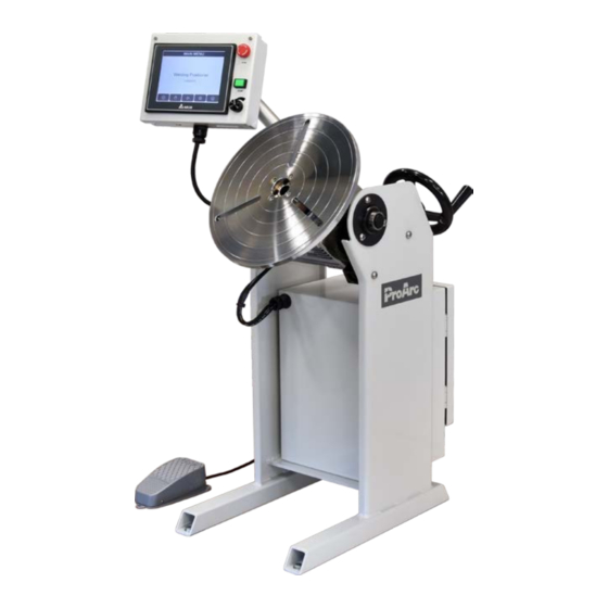
MODEL:PT‒200s
WELDING POSITIONER
Serial Number:202103005 ~ Later
Revised Date:Apr. 07, 2021
UNITED PROARC CORPORATION
th
No. 3 Gungye 10
Road, Pingjen Ind. Park
Tel No: 886 3 4696600
Pingjen City, Taoyuan 324, Taiwan
Fax No: 886 3 4694499
http://www.proarc.com.tw
E-Mail: customerservice@proarc.com.tw
Advertisement
Table of Contents
Troubleshooting

Summary of Contents for ProArc PT-200s
- Page 1 Important:Read these instructions before installing, operating or servicing this product. MODEL:PT‒200s WELDING POSITIONER Serial Number:202103005 ~ Later Revised Date:Apr. 07, 2021 UNITED PROARC CORPORATION No. 3 Gungye 10 Road, Pingjen Ind. Park Tel No: 886 3 4696600 Pingjen City, Taoyuan 324, Taiwan Fax No: 886 3 4694499 http://www.proarc.com.tw...
-
Page 3: Table Of Contents
MENU Safety Instruction Instruction ........................ i Protection ........................ ii Specification 1.1 Specifications ....................1 1.2 Control Box Specification ................... 2 1.3 Connector ......................3 Operation 2.1 HMI........................6 2.2 Main Screen ...................... 7 2.3 Manual Mode ..................... 8 2.4 Auto Mode ......................9 2.5 Setting ...................... - Page 4 INSTRUCTION Read and understand the entire manual regarding the rules for users’ WARNING safety before installing, operating, or servicing the equipment. A procedure, when not properly followed, may cause injury to the WARNING operator or others in the operating area. Equipment Identification The identification number (specification or part number), model, and serial number of this unit usually appear on a nameplate attached to the control...
-
Page 5: Protection
Protection Operation and maintenance involve potential hazards. All operators and WARNING personnel should be alerted to possible hazards and precautions should be taken to prevent possible injury. Machine : Electrical ﹡ The system’s non-fuse breaker is compatible with its maximum power and main voltage. - Page 6 UNITED PROARC’s obligation under this warranty policy is expressly limited to the replace or repair, at its option, of the defected part only. ProArc’s option to repair or replacement of a defected part under this warranty shall be based on FOB Taiwan basis.
-
Page 7: Specification 1.1 Specifications
1.1 SPECIFICATION MODEL Unit PT- 200s Power Input 1 Phase 220V 50/60Hz Capacity (Horizontal / Vertical )(W) 200 / 130 Rated center of gravity(S) Rotation speed 0.01 ~ 30 Tilt range deg. 0 ~ 120 Earthing Overall length (A) Overall width (B) Overall height (C) Center to floor (D) Table diameter (E) -
Page 8: Control Box Specification
1.2 CONTROL BOX SPECIFICATION Control Model Unit CB-500 Power Requirement 1 Phase 220V 50/60Hz 3A Main power switch... -
Page 9: Connector
1.3 CONNECTOR Control box connector: HMI Box (16Pin) Start output (7Pin) Weld Machine (10Pin) Foot switch (5Pin) - Page 10 1.3 CONNECTOR HMI & Food switch connection:...
- Page 11 1.3 CONNECTOR Welding equipment connection:...
-
Page 12: Hmi
2.1 HMI OPERATION Emergency stop. Auto start / Auto stop. Pulse adjustment knob: 1. Press the pulse adjustment knob to display red flashing cursor beside Rpm and mm/min. Rotate the knob to modify speed. 2. Press the pulse adjustment knob again to display red flashing cursor beside Amperage A2(H) &... -
Page 13: Main Screen
2.2 MAIN SCREEN Switch language Chinese / English. Switch to "Manual Mode" screen. Switch to "Auto Mode" screen User level 1 clearance is required. Default user level 1 clearance password:123 Default user level 2 clearance password:456 Refer to section 「2.11 Password」 to disable auto mode password protection. Switch to "Setting"... -
Page 14: Manual Mode
2.3 MANUAL MODE Turn table current position: Foot switch. Blue field: current position. direction selection. Red field: set position. Turn table rotation per round Move to set position. (RPM) setting. Reset current position to 0. Return to beginning position. Toggle between welding/high turn table Manual activate welder. -
Page 15: Auto Mode
2.4 AUTO MODE Turn table current position according to angle & Turn table current position: diameter: Blue field: current position. Blue field: current position. Red field: set position. Red field: set position. Turn table linear speed Turn table rotation per round (mm/min) setting. -
Page 16: Setting
2.5 SETTING Switch to Program screen. Switch to Index Weld screen. Switch to system setting screen. User level 1 clearance is required. Switch to Program note screen. Default user level 1 clearance password: 123 Default user level 2 clearance password: 456 Switch to Weld Sequence screen. -
Page 17: Program Save/Load
2.6 PROGRAM SAVE/LOAD Enter the program number in No. field and press “Load” button to load the program’s welding parameter. Enter the program number and program name, the press “Save” to save the parameters. Press or button to scroll to next/previous sets of parameters. -
Page 18: Program Note
2.7 PROGRAM NOTE Enter letter or number as program reminder. 10 letters for sh ort field, 24 letters for long field. -
Page 19: Welding Sequence Setting
2.8 WELDING SEQUENCE SETTING Welder ON delay after auto start is activated. Turn table rotation delay after arc on signal is received. Dry contact output-1 ON delay after arc on signal is received. Dry contact output-2 ON delay after arc on signal is received. Dry contact output-3 ON delay after auto start is activated. -
Page 20: Welding Current Setting
2.9 WELDING CURRENT SETTING 100% amperage value setting (analog output 1). Initial current (A) Initial current level after arc ON signal is received. Main welding current. If pulse wave function is enabled, this Peak current (A) value is the peak current value. If pulse wave function is enabled, this value is the low current Valley(low) current(A) value. -
Page 21: Index Weld Setting
2.10 INDEX WELD SETTING Set number of index welding. a ~ b:Set index welding angle and speed. b ~ c:Set positioning angle and speed. Turn table jog operation. Move to position “b”. -
Page 22: Autorun Function
2.11 AUTORUN FUNCTION X:Disable feature. O:Enable feature. X:Turn table doesn’t wait Arc on feedback signal. Turn table start rotation T2 sec after welder on signal is active. O:Turn table waits for Arc on feedback signal. Turn table start rotation T2 sec after receiving arc on feedback. Reset current position to 0 when auto start is activated. -
Page 23: Password Setting
2.12 PASSWORD SETTING User level 2 clearance is required. Default user level 1 clearance password:123 Default user level 2 clearance password:456 User level 1 clearance is required. Disable auto mode password protection. -
Page 24: Program Backup
2.13 PROGRAM BACKUP Export all 100 welding setting and store into USB (does not include program note). Import all 100 welding setting and store into system. USB (does not include program note). Stop USB function. Activate this function before extract USB. -
Page 25: System Setting
2.14 SYSTEM SETTING Time adjustment. Position setting. Backlight calibration function. Speed setting. Touch screen calibration. Maximum rotation speed limitation. Metric / inch unit setting. Minimum rotation speed limitation. -
Page 26: System Information
2.15 SYSTEM INFORMATION 1. Motor type 2. HMI software version 3. HMI file name 4. PLC software version 5. PLC file name HMI update function. PLC update function. Switch to I/O monitor screen, Switch to Error History screen. -
Page 27: Hmi Update
2.16 HMI UPDATE 1. Copy HMI update program (HMI_AutoUP) into USB disk (FAT32 format). 2. Insert the USB disk into USB port behind HMI display 3. Wait for a few second and system would automatically search for HMI AutoUP files 4. -
Page 28: Plc Update
2.17 PLC UPDATE 1. Copy PLC update program(CB500PT01.dvp) into a USB disk (FAT32 format). 2. Insert the USB disk into USB port behind HMI display. 3. Press ”PLC download” button, and a keypad is shown 4. Enter the password 5. Press ”YES” in the following prompt to download the PLC program Success or failure message is displayed afterward. -
Page 29: Alarm History
2.18 ALARM HISTORY 1. Alarm history record up to 1000 system error. The history can’t be deleted. 2. Left most column「O」indicates the moment error appears,「X」indicates the moment error is reset. 3. Second/third column is the time and date of occurred error. 4. -
Page 30: I/O Monitor
2.19 I/O MONITOR System I/O status, For troubleshooting/installation purpose. -
Page 31: Troubleshooting 3.1 Error Message
3.1 ERROR MESSAGE 1. Alarm window appears whenever a system error/problem has occurred. 2. Reset button: Clear the system problem first before pressing reset button. Reset button only attempts to reset system error. If problem is still present while pressing the reset button, the window could reappear immediately after. -
Page 32: Troubleshooting
3.2 TROUBLESHOOTING Error Code Error Message Description PLC battery voltage is too low, malfunctioned, or absent 1. Check if PLC’s battery LED indicator on front cover is flashing. 2. Check if PLC’s battery is absent. Solution: Replace/Add battery A.S.A.P. M480 PLC Low Battery Note: The error message can’t be disabled before the battery problem is fixed, but the system is still functional. -
Page 33: Parameters 4.1 Pt Servo Amplifier Parameters
4.1 PT SERVO AMPLIFIER PARAMETERS Parameter Setting P1-00 0002 P1-01 0100 P1-44 192000 P1-45 P2-10 0101 P2-11 0100 P2-14 0100 P2-15 0100 P2-16 0100 P2-17 0100 P2-18 0101 P2-19 0105 P2-20 0109 P2-21 0007 P2-22 0103... -
Page 34: Part List 5.1 Part List - Pt200S Mechanism
5.1 PART LIST ― PT-200s (MECHANISM) Item. Part No. Description Q’ty. Remark 0312-0501 Shaft 0331-2003 Self-lubricating bushing * 0353-0356 Worm reducer * 0364-0206 Servo Motor 3053-1002 Tilting hand wheel 5010-1010100-10 Faceplate 5010-2040010-20 Grounding brush w/ conducting seat 5012-2350000-20 Tilting worm shaft... -
Page 35: Part List - Hmi And Remote
5.2 PAT LIST ― HMI BOX Item. Part No. Description Q’ty. Remark 2505-0022-01 HMI & Software 3214-2009 E.S Push button 3271-2005 Push button 3216-0004 Knob 3169-1223 Rotational with switch encoder * Recommended spare parts... -
Page 36: Part List - Control Box
5.3 PART LIST ‒ CONTROL BOX (INTERNAL) Part No. Description Q’ty. Remark Item. 3013-0006 Analog output module 2505-0021-01 PLC & Software 3017-0007 Power supply 3031-2212 Servo amplifier 3251-4207 Relay with terminal 3331-2002 IEC Inlet filter 3121-6002 Plug male (10Pin) 3122-4004 Socket female (10Pin) 3121-4003 Plug male (7Pin) -
Page 37: Circuit 6 Circuit
6. CIRCUIT... - Page 38 6. CIRCUIT...
- Page 39 6. CIRCUIT...
Need help?
Do you have a question about the PT-200s and is the answer not in the manual?
Questions and answers