Table of Contents
Advertisement
Quick Links
Advertisement
Table of Contents

Subscribe to Our Youtube Channel
Summary of Contents for Condec Source 3000
- Page 1 Presented By Dallas Ft Worth Austin Houston NicolScales.com 800.225.8181 Contact Us Nicol Scales & Measurement is an ISO Accredited Calibration Company that has provided calibration, repair and sales of all types of weighing and measurement products since 1931.
- Page 2 Source 3000 Self-Contained Pressure Source Console Operation and Maintenance Manual 65546...
- Page 3 Source 3000 Operation and Maintenance Manual...
-
Page 4: Table Of Contents
3.3 Orion 2C Valve Assembly Parts List ..........13 Specifications ..........................16 Source 3000 Warranty and Return Policy ..................... 17 Source 3000 Return Material Authorization Form................. 18 Copyright ©... - Page 5 Source 3000 Operation and Maintenance Manual...
-
Page 6: About This Manual
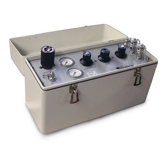
About This Manual The Source 3000 is a portable, self-contained pneumatic pressure console with precision vernier. A rugged, compact instrument manufactured by Condec, designed to provide ease of operation when used in conjunction with multiple manufacturers electronic calibrators, for the calibration of a wide variety of pressure sensing and measuring devices. - Page 7 The heart of the Source 3000 are the two micro-metering valves and the vernier provided for control of the internal nitrogen source. Overpressure protection is provided by a fully adjustable pressure regulator which is manually set for each new device being tested. The Source 3000 is designed for compatibility with all major manufacturer’s electronic calibration equipment.
-
Page 8: Operation
Operation Pressure Cylinder Filling To initially fill or refill the internal pressure cylinder (3000 PSI max.) of the Source 3000, see Figure 2-1 below and proceed as described below. NOTE: The pressure cylinder used as the filling source must be regulated to provide a maximum output of 3049 PSIG. -
Page 9: Initial Setup
final value may be quickly achieved. 3. To obtain exact pressure readings, slowly rotate the control (3) knob in the direction required VERNIER (clockwise to increase pressure) as indicated by the electronic standard display. Source 3000 Operation and Maintenance Manual... -
Page 10: Maintenance
Table 3-1. Source 3000 Troubleshooting Maintenance Procedures This section outlines the mechanical repair procedures for the Source 3000 pressure source. The repair procedures cover the major components and subassemblies which are critical to the proper functioning of the calibrators and that will likely need periodic maintenance over the life of the unit. Only those persons who are formally trained as skilled technicians should attempt to repair these units. -
Page 11: Installing New Nitrogen Cylinder Assembly (Pn 65622)
No. 43 drill bit No. 4-40 tap tap handle small hammer NOTE: See Table 3-2 on page 13 and Figure 3-3 on page 15 for additional parts information. Source 3000 Operation and Maintenance Manual... -
Page 12: Orion 2C Manifold, Vernier Control Disassembly
1. Secure the manifold by its center portion, in a bench vise, with the valve knobs pointing upward. 2. Using the .061" hex wrench, loosen and remove the knob inserts (4) from the pressure and vent valve stems. 3. Loosen the 3/4" locknuts (1) on the pressure and vent valve threaded needle housings (10). 4. -
Page 13: Orion 2C Manifold, Vernier Control Reassembly
fluorinated Krytox grease to the needle threads before reassembly. 7. Assemble the needle into the valve housing and turn it until it stops. 8. Reinstall the needle/housing assembly into the valve cavity until finger tight. Source 3000 Operation and Maintenance Manual... -
Page 14: Orion 2C Manifold, Panel Installation
9. Mount the manifold body (16) in a vise. For the pressure and vent valves only, torque the needle/housing assembly to 325 in-lb. using the needle housing socket (PN 65580). 10. Install the housing lock nuts (1) onto the housing (10) and tighten until snug with the 3/4" socket. 11. -
Page 15: Pressure Limit Control (Pn 65455), Regulator Removal
1/2" from the panel surface, then tighten the cap screw on the mounting collar. 4. Fill the cylinder to approximately 1000 PSIG and check all fittings for leaks. See Section 2.1 on page 3 for cylinder refilling procedure. Source 3000 Operation and Maintenance Manual... -
Page 16: Panel Gage Removal
3.2.13 Panel Gage Removal Tools required: Phillips screwdriver 7/16" wrench 9/16 " wrench 1. Vent any remaining gas from the nitrogen cylinder to atmosphere. 2. Remove front panel from its enclosure as described in Section 3.2.1 on page 5, and carefully place on a bench top. -
Page 17: Port 1, Port 2 And Fill Port Filter (Pn 54188)
2. Remove front panel from its enclosure as described in Section 3.2.1 on page 5 and place on a bench top. 3. Loosen and remove the tubing end nuts from the tee fitting (PN 65386). Source 3000 Operation and Maintenance Manual... -
Page 18: Orion 2C Valve Assembly Parts List
4. Remove the male reducing adapter/run tee assembly from the check valve. 5. Remove the check valve from the female elbow fitting. Remove any remnants of Teflon tape from the pipe threads. Note direction of flow arrow. Check Valve Disassembly 1. - Page 19 Table 3-2. Orion 2C Valve Assembly Parts List INSERT LOCK SCREW INSERT O-RING (PN 66654) POPPET SPRING BODY Figure 3-1. Standard Pneumatic Regulator (PN 65455) Figure 3-2. Nitrogen Inlet Check Valve Assembly (PN 60263) Source 3000 Operation and Maintenance Manual...
- Page 20 25/2X 23/2X 24/3X 35/2X 21/14 25/2X 26/2X Figure 3-3. Orion 2C, Exploded View Maintenance...
-
Page 21: Specifications
Specifications Pressure Specifications: Pressure Hose Fittings: Pressure range: Based on vendor’s electronics Quantity Supplied: Three; one input, two test port fittings. Available pressure calibrations: Style: Input fitting: 1/4" 37° female AN swivel one end, 1/8 NPT male on the other Gage only, absolute only, or Test port fittings: Quick disconnect gage and absolute... -
Page 22: Source 3000 Warranty And Return Policy
Source 3000 Warranty and Return Policy If possible, please save original packing material which is specifically designed for the unit. Should it be necessary to ship the unit back to the factory, a suitable shipping container must be used along with sufficient packing material. -
Page 23: Source 3000 Return Material Authorization Form
) NO SHIP TO Address: COMPANY NAME: STREET: CITY, STATE, ZIP: ATTN: CONDEC • 3 SIMM LANE • DOOR D, UNIT 2A • NEWTOWN, CT 06470 ATTN: PRESSURE PRODUCTS/REPAIR LAB TEL: 888-295-8475 • FAX: 203-364-1556 or 715-234-6967 WEB SITE: www.4condec.com Specifications...
Need help?
Do you have a question about the Source 3000 and is the answer not in the manual?
Questions and answers