
Related Manuals for REMBE Q-Rohr-3


Summary of Contents for REMBE Q-Rohr-3
- Page 1 ® Q-Rohr English translation of original German operating manual USB-QR3-13801/0...
-
Page 2: Table Of Contents
Availability Monitoring the release alarm signal Table of contents ............20 Introduction ........3 Action to be taken after a release .. 20 1.1 Availability ............3 ® 10 Dismantling the Q-Rohr -3 ..... 21 1.2 Style conventions used in the text ....3 10.1 Personnel qualifications for dismantling .. -
Page 3: Introduction
Availability English translation 1 Introduction of original German operating Thank you for choosing to buy this top quality product ® from REMBE designed to provide protection against manual explosions. The following instructions are intended to help you use ® the Q-Rohr -3 properly, safely and economically. -
Page 4: Safety
® warnings in the text The Q-Rohr -3 is only permitted to be used under the ® operational conditions specified by REMBE . Information can be found in the section Conditions for safe use starting DANGER on page 7. Information or instructions... -
Page 5: Information About Residual Dangers
Information about residual dangers ® 2.4 Information about residual Before the Q-Rohr -3 is used, the operator or person authorized by the operator must dangers ® ensure that the Q-Rohr -3 will be utilized for ® The Q-Rohr -3 has been constructed in accordance its proper use and that all safety regulations with the latest state-of-the-art technology and will be complied with. -
Page 6: Personal Protective Measures
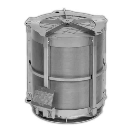
Description You are not allowed to replace rupture discs 3.1 Function ® yourself until you have consulted REMBE ® The Q-Rohr -3 is comprised of a stainless steel You are not allowed to use any rupture discs mesh flame trap and an upstream rupture disc. The which have not been approved for the rupture disc is designed for a specific burst rating. -
Page 7: Information On The Rating Plate
® Flange -3 under the operating conditions specified by Gasket ® REMBE Rupture disc with signal unit ® The Q-Rohr -3 has a safety function which is a Carrying fixture with hoist eyebolts requirement for the operation of the equipment. It is... -
Page 8: Conditions At The Point Of Operation
8.2 ft (2.5m) around the outer edges of the equipment is not permitted in this confined area. ® Q-Rohr Deviations from the aforementioned operating conditions are permissible, but require explicit ® written confirmation from REMBE USB-QR3-13801/0... -
Page 9: Conditions For Installation
® release is relatively low compared to a fire. of the flange, please contact REMBE Customer Service. For an overview of the flange dimensions and boreholes, please refer to the Appendix starting on page 28. - Page 10 Conditions for safe use ® The Q-Rohr -3 absorbs the energy of the explosion DANGER in a similar way to a heat exchanger. The ® temperature of the surface of the Q-Rohr Risk of injury due to secondary therefore rises after a certain period of time, but it reactions when the equipment is remains below the minimum ignition temperature of ®...
-
Page 11: Volumetric Limits
Volumetric limits 4.6 Volumetric limits ® Each Q-Rohr -3 is only capable of providing protection for the specified volume given in each case. Additionally, a distinction is made between venting in a potentially explosive area falling under Zone 22 in accordance with ATEX Directive 1999/92/EC;... - Page 12 10.0 m³ 935.83 ft³ 26.5 m³ ® *For higher volumes or different parameters, please contact REMBE , INC MIE = Minimum ignition energy of the dust in the facility MIT = Minimum ignition temperature of the dust in the facility...
- Page 13 Volumetric limits ® 4.6.3 Maximum individual volumes per Q-Rohr -3 for hybrid mixtures No zone Kst-value: ≤ 180 bar × m/s Dust: MIE > 3 mJ ® Q-Rohr MIT ≥ 370 C/698 KG-value: ≤ 100 bar × m/s Gas: MESG: ≥ 0.95 mm Nominal Pred, max: ≤...
-
Page 14: Transporting The Q-Rohr -3
Transporting the Q-Rohr®-3 ® 5.3 Transporting 5 Transporting the Q-Rohr ® The Q-Rohr -3 can be transported in its original CAUTION packaging (packaging in which it was delivered) to where it is to be used. Observe the following safety Risk of injury due to loads moving in information, especially for heavy weights. -
Page 15: Installing The Q-Rohr -3
Safety information for installation ® Transport the Q-Rohr -3 only by the hoist eyebolts provided for this purpose on the carrying fixtures. Use at least two of the hoist eyebolts. ® To lift and transport the Q-Rohr -3, follow the instructions in the section Transporting the Q-Rohr®-3 starting on page 14. -
Page 16: Installation
(i.e. If the gasket is damaged, replace it with an with the flange at the side), depending on the ® original REMBE spare part. specific installation situation. The spare part number for the gasket can be found in the List of spare parts starting on page 36. - Page 17 Installation ATTENTION ATTENTION Risk of damage to the flange and Risk of damage to the flange, erection bolts due to tightening with container and facility due to recoil incorrect torque. forces from explosions. Use a torque wrench. Make sure that the flange and the container are capable of ...
-
Page 18: Installing And Connecting The Intrinsic Safety Isolated Barrier
Installing and connecting the intrinsic safety isolated barrier 7.2 Connecting the signal line from 7 Installing and connecting ® the Q-Rohr -3 to the intrinsic the intrinsic safety isolated safety isolated barrier barrier DANGER The intrinsic safety isolated barrier which is included in delivery monitors the condition of the rupture disc. - Page 19 Connecting the signal line from the Q-Rohr®-3 to the intrinsic safety isolated barrier 7.2.1 Preparations for connection Open the connection box (2). The intrinsic safety isolated barrier must be connected in such a way that it shuts down 7.2.2 Connecting the rupture disc monitor the facility immediately if the rupture disc...
-
Page 20: Monitoring The Release Alarm Signal
Check the status of the Q-Rohr ® ® and contact REMBE Customer If the wiring has been done correctly, the intrinsic Service to check what to do next. safety isolated barrier controls a visual or acoustic release alarm signal. -
Page 21: Dismantling The Q-Rohr -3
Cordon off the area with barrier tape. any media and is unpressurized. To coordinate further procedures, contact Make sure that there is no risk of explosion. ® REMBE Customer Service. Make sure that there are no unauthorized ® Make the Q-Rohr... -
Page 22: Tools For Dismantling
Dismantling the Q-Rohr®-3 Secure the facility to prevent it being switched 10.3 Tools for dismantling on again accidentally. The following tools and materials are required for Make sure that the facility does not contain dismantling work: any media and is unpressurized. ... -
Page 23: Cleaning The Q-Rohr -3
(1) and for If the outside of the filter packing for the Q-Rohr-3 deposits of dust to get caked on. To ensure that the gets heavily soiled, we recommend that you use the ®... -
Page 24: Tools For Making Ready For Use Again
Make sure that there is no risk of explosion. ® Obtain an original REMBE Make sure that there are no unauthorized rupture disc to persons within the area of the facility to be replace the one which has burst. The new dismantled. - Page 25 -3 with ® deposits stuck in the Q-Rohr -3 using a brush any bare parts of the body. ® and high-pressure washer, contact REMBE Wear protective clothing in Customer Service. accordance with EN 533. ® Dry the Q-Rohr...
- Page 26 Feed the signal line (2) carefully through the ® Only use original REMBE gaskets. cable gland (3) to the connection box (6) as Only use gaskets which accord shown in the illustration.
-
Page 27: Storing The Q-Rohr -3
Contact the competent local authority for detailed information on disposal. If you have any questions ® about the materials used, please contact REMBE Customer Service. To dispose of all parts in an environmentally-friendly manner, you have to sort the parts. -
Page 28: Appendix
Technical data 17 Appendix 17.1 Technical data Recommended Type DN/Size bolts Weight (8.8 or [in] [mm] [in] [mm] [in] [mm] [in] [mm] [in] [mm] [in] [mm] equivalent) [lbs] [kg] ® 200/8“ Q-Rohr -3-8 23.62 16.14 13.78 10.55 9.57 0.33 55.13 ®... -
Page 29: Flanges
Flanges 17.2 Flanges Angular ring Nominal width Holes Angular ring [mm] [in] [in ] [mm] [in ] [mm] [in ] [mm] [in ] [mm] [in ] [mm] [in ] [mm] 8“ 8.19 10.24 9.57 1.18 12“ 12.20 14.57 13.98 11,0 1.57 16“... -
Page 30: Technical Data For The Kfd2-Sr2-Ex1.W Intrinsic Safety Isolating Barrier
Appendix 17.3 Technical data for the KFD2-SR2-Ex1.W intrinsic safety isolating barrier (for further information see www.pepperl-fuchs.com) Features 1-channel isolated barrier 24 V DC supply (Power Rail) Dry contact or NAMUR inputs Relay contact output Line fault detection (LFD) ... - Page 31 Technical data for the KFD2-SR2-Ex1.W intrinsic safety isolating barrier 17.3.1 Connection Class II. Div. 2 17.3.2 Technical data General specifications Signal type Digital Input Supply Connection Power Rail or terminals 14+, 15- Rated voltage 20 ... 30 V DC ≤ 10 % Ripple ≤...
- Page 32 Appendix Directive conformity Electromagnetic compatibility Directive 2004/108/EC EN 61326-1:2006 Low voltage Directive 2006/95/EC EN 61010-1:2010 Conformity Electromagnetic compatibility NE 21:2006 Protection degree IEC 60529:2001 Input EN 60947-5-6:2000 Ambient conditions Ambient temperature -20 ... 60 °C (-4 ... 140 °F) Mechanical specifications Protection degree IP20 Mass...
- Page 33 Technical data for the KFD2-SR2-Ex1.W intrinsic safety isolating barrier Group, category, type II 3G Ex nA nC IIC T4 of protection, temperature class Output 50 V AC/4 A/cos ᶲ > 0.7; 40 V DC/2 A resistive load Contact loading Electrical isolation Input/Output safe electrical isolation acc.
- Page 34 Appendix 17.3.3 Configuration Switch position Function Position Mode of operation with high input current Output I (relay) with low input current energized no function Line fault detection Operating status Control circuit Input signal Initiator high impedance/contact opened low input current Initiator low impedance/contact closed High input current Lead breakage, lead short-circuit...
- Page 35 Technical data for the KFD2-SR2-Ex1.W intrinsic safety isolating barrier 17.3.4 Accessories Power feed module KFD2-EB2 The power feed module is used to supply the devices with 24 V DC via the Power Rail. The fuse-protected power feed module can supply up to 150 individual devices depending on the power consumption of the devices.
-
Page 36: Spare Parts
Appendix 17.4 Spare parts When you place your spare parts order with us, please tell us the BATCH number on the rating plate. Item Spare parts Designation Addition Replacement rupture disc Intrinsic safety isolated barrier 1.2.1 KFD2-SR2-Ex1.W Standard 1.2.2 KFD2-SR2-Ex1.W.LB Alternative 1.2.3 KFA5-SR2-Ex1.W... - Page 37 Annual Inspection Form USB-QR3-13801/0...
- Page 38 Appendix USB-QR3-13801/0...
-
Page 39: Contact Details For The Manufacturer
Contact details for the manufacturer 17.6 Contact details for the manufacturer USB-QR3-13801/0...
Need help?
Do you have a question about the Q-Rohr-3 and is the answer not in the manual?
Questions and answers