Table of Contents
Advertisement
Quick Links
User Manual
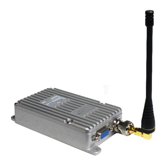
RF Audio/Data Modem
MD-100D VHF
MD-400D UHF
YeonHwa M Tech Co.,Ltd
36, Jeonpa-ro 44beon-gil, Manan-gu, Anyang-si, Gyeonggi-do, Korea 14086
www.xradio.co.kr
Email : sales1@xradio.co.kr
1. MD-100D/400D Digital RF Modem Main Functions
The MD-100D / 400D digital RF modem has standardized the external appearance and connector
specifications to maintain compatibility with existing analog modems.
It also supports voice call and data communication with DMR transceiver and standard.
When making a voice call, use external microphone and speaker as same as existing digital radio.
It is possible to use transmitter and receiver as a single device when it is used for the village
broadcasting.
In case of data communication, it can be used as a general data modem and it is designed to use AT
COMMAND.
Advertisement
Table of Contents

Summary of Contents for XRadio MD-100D Series
- Page 1 YeonHwa M Tech Co.,Ltd 36, Jeonpa-ro 44beon-gil, Manan-gu, Anyang-si, Gyeonggi-do, Korea 14086 www.xradio.co.kr Email : sales1@xradio.co.kr 1. MD-100D/400D Digital RF Modem Main Functions The MD-100D / 400D digital RF modem has standardized the external appearance and connector specifications to maintain compatibility with existing analog modems.
-
Page 2: General Information
MD-100D / 400D supports dual (analog / digital) mode. It is compatible with existing analog modem or transceiver. When using digital mode, it is very efficient in data error, clean sound quality and volume, distance and usage time. 32 channel can be selected by using internal DIP switch. MD-100D/400D Series main functions are below, ... -
Page 3: Transmitter Specifications
Transmitter Specifications RF Output VHF : 10/2 Watt, UHF : 5/2Watt Spurious and Harmonic 70dB FM Hum and Noise 40dB (12.5KHz) Audio Distortion Less than 3% Audio Characteristics +1, -3dB from 6dB per octave pre-emphasis Characteristic from 300 ~ 3000Hz 50ohms Output Impedance 3. - Page 4 3.4 D-SUB 15Pin Connector Specification Pin NO Pin Name Pin Description Not use Not use Low Active DC12V DC+12V Carrier Detector MIC_IN 30mV @ 2KHz Dev FLASH_PRO SPEAKER_OUT 300mV @ 1KHz dEV RX_DATA 3.3V TTL TX_DATA 3.3V TTL GPS_TX_DATA 3.3V TTL Ground Ground GPS_RX_DATA...
- Page 5 3.5 MD-100D/400D Drawing Figure 3-4) MD-100D/400D Drawing...
-
Page 6: How To Set Dip Switch
4. How to set DIP Switch 4.1. Dip switch setting Picture 4-1) Dip Switch TX Power setting and channel setting 4.2 TX Power Setting TX Power is changed by Switch No.6 Factory default TX Power value is High Dip Switch Power Value Low Power High Power... - Page 7 00001 00010 00011 00100 00101 00110 00111 01000 01001 01010 01011 01100 01101 01110 01111 10000 10001 10010 10011 10100 10101 10110 10111 11000 11001 11010 11011 11100 11101 11110 11111 5. MD-100D/400D Operation Mode MD-100D / 400D supports 3 modes: 1) AT Command mode and 2) continuous mode for keyboard input or file transfer using Tera term.
-
Page 8: At Command Interface
MD-100D/400D operation mode 1) AT Command mode 2) 3 Wires continuous mode -. Operates in 3 Wire Mode (TXD, RXD, GND). 3) 5 Wires continuous mode (used for many data transmission) -. Supports H / W flow control using TXD, RXD, CTS, RTS, GND. When the MD-100D / 400D data modem is booted for the first time, AT Command mode is set. - Page 9 AT*VOL=<value> SET VOLUME(<value>)=(<value>) Parameters 1 ~ 16 AT*VOL? GET VOLUME(15)=(150) Example AT*VOL=5 SET VOLUME(5)=(47) 6.5 OID OWN ID setting is available only in CPS program, and can be checked in AT Command only. Description Command for checking OWN ID AT*OID? Query OID:00000001 Answer...
- Page 10 CID[<index>]:<call id>,CF:<call format> [반복] CALLID OK AT*CID=1 SET CUR-CID:01 CID[01]:00000002,CF:GRP CALLID OK Parameters AT*CID? CID[00]:00000001,CF:GRP CID[01]:00000002,CF:GRP Example CID[02]:00000003,CF:GRP CID[03]:00000010,CF:GRP CID[04]:********,CF:ALL CALLID OK 6.9 CHSET Channel setting command (When this command is used, channel value Description changed by DIP Switch is ignored.) AT*CHSET=<channel number>...
- Page 11 It is set according to Dip switch 6 at boot, and it can be changed with this command. AT*PWRLEVEL? GET PWRLEVEL=<value> Query Answer AT*PWRLEVEL=<value> SET PWRLEVEL=<value> 0 : Low Power Parameters 1 : High Power AT*PWRLEVEL? GET PWRLEVEL=0 Example AT*PWRLEVEL=1 SET PWRLEVEL=1 6.13 VERSION Description...
- Page 12 AIR data transfer structure Since the DMR Data Modem operates in 2: 1 mode, the actual transmission is as follows. 2:1 TDMA : There are two slots (slot1, slot2(30m/s) in a single channel so it operates as the below picture. Figure 2: 1 TDMA structure 3.
- Page 13 When RTS is "LOW" (when the MD-100D/400D modem's serial buffer has space): The PC or external device sends normal serial data to the modem. When RTS is "High" (when the serial buffer of the MD-100D/400D modem is full): it stops sending serial data to the external device.
- Page 14 5. D-SUB 15Pin Change connector specification 1) 5 Pin : GPIO1 → 12Pin : SERIAL_BUSY → Pin NO Pin Name Pin Description Not use (Not use CTCSS/DCS) Not use (Not use CTCSS/DCS) Low Active Vin(DC12V) DC+12V GPIO1 → I/O→I Carrier Detector MIC_IN 30mV @ 2KHz Dev FLASH_PRO...
- Page 15 5. For Safe Operation 5.1 Precautions Do not remove the antenna from the radio or do not transform the antenna or do not make any changes on the antenna. The strong electronic wave to be emitted from the radio can have an effect on the performance of the radio and can cause the radio to have a defect.
-
Page 16: Safety Notes
Please do not use the radio at the place where computer or other electric/electronic devices are being used. The strong electronic wave from the radio can have an effect on the equipment. Safety Notes Please make sure to read the followings above for safe and effective use of the radio. •... - Page 17 Usage Application ▪ Water/Waste Treatment ▪ Plants Oil and Gas Field, SCADA ▪ Security/Alarm System ▪ Gate Systems, Remote Controls ▪ Commercial Sign Control ▪ Automatic Vehicle Location ▪ Murphy/Kill Switches ▪ Weather Monitoring ▪ Irrigation Systems ▪ Emergency Call Boxes ▪...
-
Page 18: Warranty Statement
Warranty Statement Thank you for purchasing MD-100D/ MD-400D Series. 1. This product has passed strict quality control and testing process by YeonHwa M Tech. 2. Warranty is one year from the day of release. • When there is malfunction of the product under normal operating conditions during the warranty period, your authorized dealer and the service center will repair it free of charge.