
Summary of Contents for Kilews KL - CTDS
- Page 1 BNK 電動起子扭力顯示盒使用手冊 Torque Display User Manual Model : KL - CTDS (Ver 2.00) 奇力速工業股份有限公司 KILEWS INDUSTRIAL CO., LTD. http://www.kilews.com.tw Y2F167-2-018 20200323-V2127...
-
Page 2: Panel Function
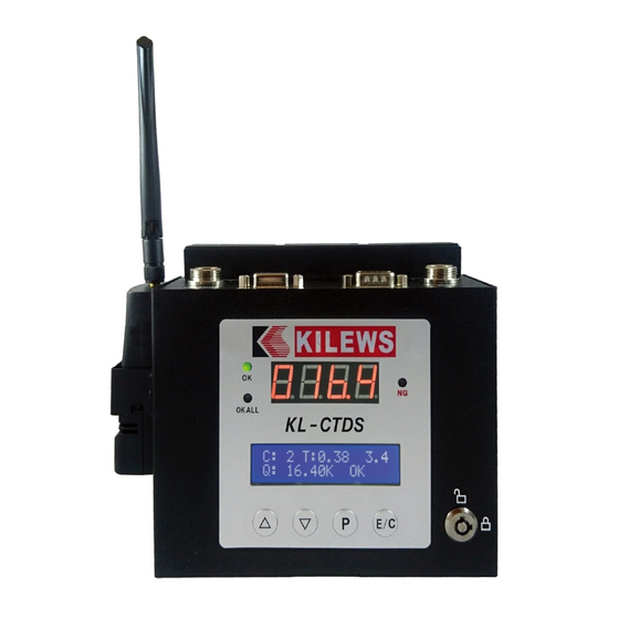
1. Panel Function Display screen: 1. Four-digit seven-segment display of torque value 2. 16X2 LCM display setting function C: Display count value T: Display screwdriver action time 999.9 display number of turns Q: Display torque value S: Display status (OK, NGT, NGQ, NGC, OKALL..) ... - Page 3 Screwdriver port Power port (4PIN) RS232/PORT1 RS232/PORT2 (6PIN) BNK series BN Anti-interference Connect Barcode SKP-BE32HL Connect DAS small torque cable Scanner SKP-40B-HL-800 BNK series BN Anti-interference Connect Barcode Connect DAS power torque cable Scanner SKP-40B-HL (BNK800 series) Remark: Please switch the power controller HI/LO switch to "HI" position.
- Page 4 2. Set Function Options and Operating Instructions After switching on the power, to enter into the function menu, press the “P” key on the panel for 3 seconds, following which password input is required to enter the menu. Set Up Time and Factory Setting Name Function Interpretation...
- Page 5 NS STOP ON/OFF Set up the handling method selected during errors of the screwdriver. Set up for ON: when there is error signal, display NS stops the action of the screwdriver immediately. The user is required to press the “E/C” key for confirmation in order to unlock the forward rotation (For I/O control, input “CONFIRM”...
-
Page 6: Operation
FINDING OFF: NG will display when no load rotation GATE MODE OFF/ONCE/TWICE/ ONCE: workpiece in position at once ONCE+CON/TWICE TWICE: workpiece in position at two times +CON ONCE+CON: workpiece at position at once plus CONFIRM for confirmation TWICE+CON: workpiece at position at two times plus CONFIRM for confirmation TORQUE UNIT kgf.cm/N.m/... - Page 7 3. Set function options and operating instructions 3-1. After the power is turned on, press the "E / C" button for 3 seconds to enter the menu of initial default, which must entry the password to enter. LOAD DEFAULT NO/DEFAULT Cancel/restore to factory setting 3-2.
- Page 8 5. External Output Control Function Description Connector No. Function Description Remarks RUN FWD: During the switch-on of screwdriver, CN1, 2 are conducted CN 1 START During close circuit, CN1-CN2 are conducted During open circuit, CN1-CN2 are disconnected GND: CN 2 This pin refers to the RUN FWD signal connection negative end Brake: When the brake of the screwdriver is actuated, CN3, 4 are conducted...
-
Page 9: Confirm Mode
6. CONFIRM Mode Code Description Remarks Refers to a switch SENSOR confirmation method External sensor switch Refers to two switch SENSORS In case of errors, SENSOR needs to be in detection, and the panel displays External sensor switch “Er”; the “CONIRM” on the panel needs to be pressed again or the external confirmation (CN7+CN8 close circuit) in order to clear the “Er”... -
Page 10: Serial Interface
9. BARCODE instructions: 9-1. Hardware description Connect Bar code Reader to port 1 on CTDS through RS232 9-2. Barcode Reader Set function options <Serial interface> Record Suffix ===>CR Baud Rate ===>9600 BPS <Data Frame> Data Bits ===>8 Parity ===>None Stop Bits ===>1... - Page 11 9-3.1. Set fasten program command on CTDS first The program that can be used to switch the fasten program through Barcode Reader Use KILEWS barcode for Program switching, 1-99 groups can be switched (CMD.P01-CMD.P99) Instructions: 99 sets of programs have been preset on the CTDS. The barcode of the group to be used must be pasted on the workpiece in advance.
- Page 12 4、Please do not modify the connection ports and contacts to avoid malfunctions or poor quality and confirm with the KILEWS before you try to change or modify any of them. Please be noted that all the guarantees will be invalid if you change the ports and contacts without authorization. KILEWS will not responsible for it.
-
Page 13: Grounding Instructions
2、Do not pull the cable tightly, place it close to oil, chemicals, or hot objects. Also, be careful not to scratch the cable to sharp objects during operation. 3、The KL-CTDS can only be used exclusively for KILEWS power supply, BNK electric screwdriver and accessories. Do not use the electric screwdriver driver for other machines. - Page 14 CTDS V2.0/MCTDS5 Data transmission description and flow control suggestion VER:2020060201 1. Controller power on and time synchronization After controller is power on, it will send data {REQ0...} each second to inform external device such as computer、PLC、AMS. It needs to reply {CMD0,..} that controller function normally and controller time.
- Page 15 Cyclic communication Controller write to external device REQ0(send/sec.) Controller respond time CMD0(send/sec.) Controller External device Barcode input to controller REQ1 CTDS/MCTDS5 PC/AMS/PLC Controller feedback time (Master) (Slave) CMD0 Data write in to controller DATA0(check column 6 if it’s new data) Controller feedback time CMD0...
- Page 16 Kilews KL-CTDS-2.0&KL-MCTDS5 Basic Data Output Protocol Description (Ver1.0_20210302_01) COMPORT Setting:Baud rate : 115200/9600(CTDS 1.7X), Data bit : 8 , Stop bit : 1, Parity bit :NON Serial communication Mode -ASCII (American Standard Code for Information Interchange) There are three basic data output formats send from device (CTDS/MCTDS) to external system (DAS/AMS/Other System) via the buildin RS232 port on the device : 1.Command {REQ0} : Send from Device to Host (Send device status to host per second after device startup ready)
- Page 17 Mode: 0 : ADV (Connection mode), 16 Device Operation Mode 1 Byte 1 : STD (Standalone Mode), String 2 : ALI (Alignment mode) , 3 : SET(Setting mode) Tool Stop Status (0: None , 1:NS, 2:AS, 3:E3, 4:E4, 5:E5, 7:E7, 8:E8, 9:BS, A:EPC, B:ESC, C:ES, D:Er, E:C1, F:C2, G:C4, H:C5 I:ESD J:EA) EA has an abnormal communication in CTDS 1.7X version.
- Page 18 Power Controller MODEL: KL-CTDS-V2.0 CUSTOMER DWG NAME PRODUCTION NO. ITEM NO: DWG NO: MATERIAL SHRINK TITLE: DES. BY DATE THIRD ANGLE PROJECTION. CHKD.BY DATE UNIT SCALE SHT NO. APPD.BY DATE OF SHTS.
- Page 19 KL-CTDS-V2.0 No. PARTS NO. PARTS NAME-E PARTS NAME-C Q'ty AA50001-139N CORD ASSEMBLY (BC6Pin) 3M 連接線 BC6PIN 3M隔離線灰色 AA50005-B6P-7-2 CORD ASSEMBLY (BC6Pin&4Pin) 2M 連接線 BC6P轉4P 2M P11404-6 Key (1506) 鑰匙 (1506) P11404-8 Key Switch ASS'Y 鑰匙開關半成品 YTM0173 Sticker-Model 面板貼紙 CAA10003-1 Housung-Upside 外殼上蓋...
Need help?
Do you have a question about the KL - CTDS and is the answer not in the manual?
Questions and answers