
Summary of Contents for CAR-connect VAS 5581A
- Page 1 Operating manual D i a g n o s t i c b o x V A S 5 5 8 1 A 21.VW.2210.3063_BA_V00_EN VAS 5581A...
-
Page 2: Legal Notice
TRANSLATION OF THE ORIGINAL OPERATING MANUAL All rights reserved. All text, images and graphics are subject to copyright and other intellectual property laws. Copyright 2020 CAR-connect GmbH. Image sources Symbols for warnings, prohibitions, mandatory actions and standards are taken from publicly accessible sources, such as the Internet. -
Page 3: Table Of Contents
Intended use Requirements for the target group Duties of the operator Additional documents PRODUCT DESCRIPTION Scope of delivery Design Diagnostic box VAS 5581A/16 Power supply cable VAS 622 007 Adapter cable VAS 5581A/11 Sets Symbols and connections Displays and controls Displays... - Page 4 Finishing diagnostics Exiting diagnostics Switching off the diagnostic box Detaching the plug connections Detaching the plug connection for the diagnostic cable (32-pin) 37 Cleaning Storage and transportation Disposal Maintenance Changing the Li-ion battery pack HELP Warranty Customer service 21.VW.2210.3063_BA_V00_EN VAS 5581A...
-
Page 5: Introduction
Our portfolio also includes measurement and diagnostic technology for the entire vehicle and battery analysis equipment. With extensive experience in software and hardware development, CAR-connect is your dependable partner at every production stage, from prototyping to series production. -
Page 6: Safety
This operating manual is only valid for the following product: Item number See the “Sets” chapter. Designation Diagnostic box VAS 5581A Warning levels This chapter provides information about the warning levels used in this operating manual. DANGER Failure to observe the safety instructions WILL result in death or serious injury! -
Page 7: Important Safety Instructions
Defective and damaged products cannot guarantee protection against electrical voltage! • Do not let the product come into contact with chemicals! • Replace a defective or damaged product immediately! • Never attempt to repair or tamper with the product! 21.VW.2210.3063_BA_V00_EN VAS 5581A... -
Page 8: Safety Functions
The electrical connection to terminals 15, 30 and the pilot line and thus the electrical supply to the component being tested Communication via the VC interface The electrical connection to the universal power supply Position Description Emergency stop button 21.VW.2210.3063_BA_V00_EN VAS 5581A... -
Page 9: Intended Use
Use only the plug connections on the vehicle that the manufacturer has specified in the guided fault finding. In this operating manual, vehicle manufacturers are exclusively defined as vehicle manufacturers in the Volkswagen Group. Any use beyond what is listed here is prohibited. 21.VW.2210.3063_BA_V00_EN VAS 5581A... -
Page 10: Requirements For The Target Group
The regular inspection intervals for the diagnostic box are observed and recorded. Additional documents In addition to this document, the following documentation is also included with the product: • Spare parts page, printed document 21.CC.2210.3063_ET • Manufacturer’s documentation for universal power supply 21.VW.2210.3063_BA_V00_EN VAS 5581A... -
Page 11: Product Description
Immediately check the condition of the product and the completeness of the delivery. If anything is missing or defective, please contact the manufacturer immediately. (1) Carrying case (2) Diagnostic box VAS 5581A/16 with shock guard (3) Adapter cable VAS 5581A/11 (4) Universal power supply VAS 5581A/10 (5) Power supply cable (country-specific, see chapter “Power supply cable”) -
Page 12: Design
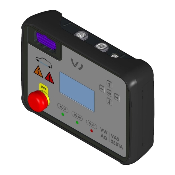
Design Diagnostic box VAS 5581A/16 Product design: (1) Main switch (2) USB 2.0 port (type B) (3) Li-ion battery pack VAS 5581A/9 (in the diagnostic box) (4) Emergency stop button (5) Warning indicators (6) OBD port (7) LC display (8) CAN port (A) -
Page 13: Power Supply Cable Vas 622 007
(7) Power supply plug type I (CN – ASE 622 007 00 074/AUS – ASE 622 007 00 026) (8) Power supply plug type M (ZA – ASE 622 007 00 030) (9) Power supply plug type N (BRA – ASE 622 007 00 066) 21.VW.2210.3063_BA_V00_EN VAS 5581A... -
Page 14: Adapter Cable Vas 5581A/11
EN | Product description Adapter cable VAS 5581A/11 (1) Ground clip (2) Low-voltage plug for MEB battery (3) Plug for diagnostic box Sets The diagnostic box is delivered as a set with a country-specific power supply cable. The following table shows the CC item numbers for the various sets. -
Page 15: Symbols And Connections
• Degree of protection • Power supply specifications You can use the serial number to track information relating to production. Port labels The following stickers identify the adjacent ports: • A: CAN port • B: Ethernet/LIN port 21.VW.2210.3063_BA_V00_EN VAS 5581A... - Page 16 The test seal identifies the product as having been approved for use in workshops and production facilities belonging to the vehicle manufacturer. QR code for accessing the operating manual on mobile devices. 21.VW.2210.3063_BA_V00_EN VAS 5581A...
-
Page 17: Displays And Controls
LED illuminated: the pilot line is closed. indicator Terminal 30 status LED illuminated: power supply to terminal 30 (+ indicator battery voltage) is active. Terminal 15 status LED illuminated: power supply to terminal 15 indicator (ignition) is active. 21.VW.2210.3063_BA_V00_EN VAS 5581A... -
Page 18: Controls
Terminal 30 (battery +) Ethernet TX - — Terminal 30C (battery +) Ethernet RX + — Pilot IN Ethernet RX - — Pilot OUT CAN Low (high-speed CAN) — — — — Terminal 30 (+ battery voltage) 21.VW.2210.3063_BA_V00_EN VAS 5581A... -
Page 19: Technical Data
Discharging: -20 ° to Max. 3 months: -20 °C to 40 °C 60 °C Max. 1 year: -20 °C to 25 °C Relative humidity 35% to 85% Condensation not permitted. Maximum permissible relative humidity: 60% in environments with corrosive gas/air. 21.VW.2210.3063_BA_V00_EN VAS 5581A... -
Page 20: Operation
• Use the product only for the applications intended by the vehicle manufacturer! CAUTION Risk of damage! Products can be damaged if they fall. • Be sure never to throw or drop the product! • Only use the product with the included shock guard! 21.VW.2210.3063_BA_V00_EN VAS 5581A... -
Page 21: Preparations
Use the diagnostic box only with the supplied shock guard. Pull the shock guard over the diagnostic box from below. The diagnostic box is now ready for operation. You can now switch on the diagnostic box. 21.VW.2210.3063_BA_V00_EN VAS 5581A... -
Page 22: Switching On The Diagnostic Box
Check the state of charge of the Li-ion battery pack. The diagnostic box is now switched on. Decide whether to connect the power supply (see chapter “Connecting the power supply/Charging the batteries”) and/or continue with operation (see chapter “Using the LC display”). 21.VW.2210.3063_BA_V00_EN VAS 5581A... -
Page 23: Connecting The Power Supply / Charging Battery Packs
Connect the power supply to the power supply socket on the diagnostic box. The display indicates that the Li-ion battery pack is charging. The power supply is now connected and the Li-ion battery pack is charging. 21.VW.2210.3063_BA_V00_EN VAS 5581A... -
Page 24: Using The Lc Display
The control keys are located to the upper right of the LC display. You can use the control keys to navigate through the menu on the LC display, make settings and change parameters. The control keys have the following functions: 21.VW.2210.3063_BA_V00_EN VAS 5581A... - Page 25 In the settings menu/operating mode menu: selects the highlighted button, which activates the corresponding function. A filled bar indicates that the function is active. Pressing the OK key again deactivates the function. 21.VW.2210.3063_BA_V00_EN VAS 5581A...
-
Page 26: Menu Structure
Gateway mode If this button is selected, the diagnostic box operates in gateway mode. The box communicates with the connected vehicle component via the microcontroller with galvanic isolation. 21.VW.2210.3063_BA_V00_EN VAS 5581A... -
Page 27: Settings Menu
In the “CAN 120Ω” state, the CAN termination resistor is set to 120 ohms. In the “CAN ∞” state, the termination resistor is set to infinite (i.e. nonexistent). Back Selecting this button exits the operating mode menu and displays the main menu. 21.VW.2210.3063_BA_V00_EN VAS 5581A... -
Page 28: Information Menu
Scroll through the pages of information by pressing the up and down direction keys. Exit the information menu and open the main menu by pressing the OK key. Display Information Meaning VAS 5581A/16 Designation of the diagnostic box. Line 1 Firmware version of the diagnostic box. Line 2 Date of the firmware version. -
Page 29: Operating Modes
In the operating mode menu, use the direction keys to highlight the “ ” button and select it with the OK key. If the selection bar in the button is filled in, the diagnostic box is operating in soft bridge mode. 21.VW.2210.3063_BA_V00_EN VAS 5581A... -
Page 30: Gateway Mode
In the operating mode menu, use the direction keys to highlight the “GW” button and select it with the OK key. If the selection bar in the button is filled in, the diagnostic box is operating in gateway mode. 21.VW.2210.3063_BA_V00_EN VAS 5581A... -
Page 31: Hard Bridge Mode
In the operating mode menu, use the direction keys to highlight the “ ” button and select it with the OK key. If the selection bar in the button is filled in, the diagnostic box is operating in hard bridge mode. 21.VW.2210.3063_BA_V00_EN VAS 5581A... -
Page 32: Starting Diagnostics
Connect the low-voltage plug to the disconnected socket of the MEB battery you want to test. Fold the locking mechanism up until it clicks into place. This pulls the plug into the plug connection. Press the lock button in (not required). 21.VW.2210.3063_BA_V00_EN VAS 5581A... -
Page 33: Activating Power Supply To The Component
In the settings menu, use the direction keys to highlight the “30” button and select it with the OK key. In the settings menu, use the direction keys to highlight the “15” button—if available— and select it with the OK key. The vehicle component is now supplied with power. 21.VW.2210.3063_BA_V00_EN VAS 5581A... -
Page 34: Configuring The Connection
• Do not touch the poles on the high-voltage battery! For certain components, it may be necessary to close the high-voltage relay to perform diagnostics. In the main menu, use the direction keys to highlight the settings menu button and select it with the OK key. 21.VW.2210.3063_BA_V00_EN VAS 5581A... -
Page 35: Setting The Can Termination Resistor
The connection must be correctly configured (see chapter “Configuring the connection”). Plug the VC interface into the OBD socket on the diagnostic box. Set up the connection to the VC interface in the diagnostic program. You can now start diagnostics in the diagnostic program. 21.VW.2210.3063_BA_V00_EN VAS 5581A... -
Page 36: Finishing Diagnostics
Switch off the diagnostic box using the main switch. The information on the LC display disappears. If previously closed, the high-voltage relay opens. If previously closed, the pilot line is interrupted. Power supply to the component being tested is interrupted. 21.VW.2210.3063_BA_V00_EN VAS 5581A... -
Page 37: Detaching The Plug Connections
Pull out the lock button. Press down the latch and fold down the locking mechanism until it clicks into place. This releases the plug from the plug connection. Pull the plug connection apart. The plug connection is now detached. 21.VW.2210.3063_BA_V00_EN VAS 5581A... -
Page 38: Cleaning
Use only a dry cloth to clean the product. Storage and transportation Store and transport the product only in the carrying case (see the “Scope of delivery” section). Disposal Observe the safety instructions! Always dispose of the product in accordance with all local disposal regulations. 21.VW.2210.3063_BA_V00_EN VAS 5581A... -
Page 39: Maintenance
• Do not short-circuit the cells and do not let the poles come into contact with conductive materials! • Do not damage or remove the sheathing around the cells! • Use only cells that have been approved by the manufacturer! • Always replace all cells at the same time! 21.VW.2210.3063_BA_V00_EN VAS 5581A... - Page 40 There are “Plus (+)” and “Minus (-)” markings etched on the circuit board, though these may be hidden by wires or other structures. • Use the main switch and the OBD socket as references when orienting the cells. 21.VW.2210.3063_BA_V00_EN VAS 5581A...
- Page 41 Use only Li-ion battery packs that have been approved by the manufacturer! Remove the shock guard from the diagnostic box. Remove the screws on the reverse side. Pull the lower shell off of the upper shell. 21.VW.2210.3063_BA_V00_EN VAS 5581A...
- Page 42 Attach the lower shell to the upper shell using the screws. 10. Pull the shock guard over the diagnostic box from below. You have now changed the Li-ion battery packs. The batteries may need to be charged. 21.VW.2210.3063_BA_V00_EN VAS 5581A...
-
Page 43: Help
Help Warranty CAR-connect GmbH grants a warranty period of 24 months from the date of purchase. The warranty is valid for demonstrable defects in functional material and workmanship. Further information on the warranty conditions can be found in the terms and conditions on the manufacturer’s website. - Page 44 Volkswagen Aktiengesellschaft K-GVO-LW Group After Sales – Group Service Literature and Systems Repair Shop Equipment PO box 011/4915 38442 Wolfsburg, Germany For internal use only Subject to technical changes Edition 06 / 2021 21.VW.2210.3063_BA_V00_EN VAS 5581A...
Need help?
Do you have a question about the VAS 5581A and is the answer not in the manual?
Questions and answers