
Related Manuals for Idex Pulseafeeder MicroVision Boiler

Summary of Contents for Idex Pulseafeeder MicroVision Boiler
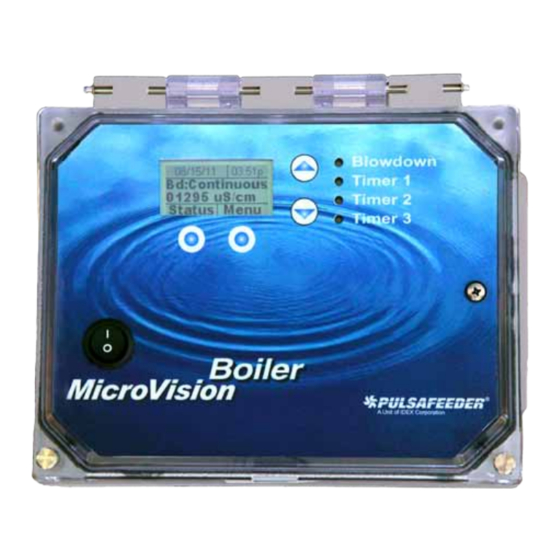
- Page 1 MicroVision Boiler MICROPROCESSOR – BASED WATER TREATMENT CONTROLLER Installation Operation Manual...
-
Page 2: Table Of Contents
TABLE OF CONTENTS INTRODUCTION ..........................3 MICROVISION FEATURES......................3 Output Relays ..........................3 Drum Levels ..........................3 4-20mA Output ......................... 4 Water Meter ..........................4 Alarm Relay ..........................4 INSTALLATION ..........................5 Location ........................... 6 Mounting Hardware........................6 Sensor Installation ........................7 TYPICAL INSTALLATION ...................... -
Page 3: Introduction
INTRODUCTION The MicroVision microprocessor-based Boiler controller has been designed to monitor and control Total Dissolved Solids (TDS) in terms of electrical conductivity measured in micro Siemens per centimeter (uS/cm). A set point of the desired conductivity is entered into the controller through the front panel. -
Page 4: 4-20Ma Output
Interlock MicroVision has a dry contact interlock option for input number 5 that will de-activate all of the control output relays upon an interlock condition indication. The interlock input requires that an auxiliary relay (not supplied) is installed across the boiler operation controls to produce a dry contact closure when the boiler is online and an open circuit when the boiler is offline. -
Page 5: Installation
INSTALLATION Opening the Enclosure Loosen the two (2) thumb screws to open the front cover of the controller, then loosen the inside panel thumb screw and carefully swing the panel to the right (Fig. 2). 72-910-24 Revision H... -
Page 6: Location
Location Select a mounting location convenient to grounded electrical and plumbing connections. It is recommended that you mount the controller on a wall or other vertical surface with adequate lighting at a comfortable level. A mounting-hole template is supplied with your controller. Installation should comply with all national, state, and local codes. -
Page 7: Sensor Installation
Sensor Installation The controller is supplied with a temperature compensated or non temperature conductivity sensor (probe). The probe location must be in a position where adequate flow is going around and through the probe (Fig. 4) so that the controller will be able to display a good measurement. -
Page 8: Typical Installation
TYPICAL INSTALLATION Fig. 5 72-910-24 Revision H... -
Page 9: Important Symbol Information
IMPORTANT SYMBOL INFORMATION Warning indicates a condition that could cause damage to both the equipment and the personnel operating it. Pay close attention to any warning. Primary Supply Ground must be connected to earth ground for safe operation of your controller. Chassis Ground –... -
Page 10: Relay Board Connections
RELAY BOARD CONNECTIONS Fig. 6 Conduit Models (Wiring High Voltage) Conduit controllers have openings for conduit connections for hard wiring. (See Fig. 6) for input and output power connections. Use only 18 AWG (1,2 mm²) stranded wire for conduit power and load connections. -
Page 11: Low Voltage Connections
LOW VOLTAGE CONNECTIONS The low voltage connections are found on the low voltage (front panel) board (Fig. 7). Use 22-24 AWG (,76 mm²) wire for: interlock, drum levels, dry alarm, and water meter connections. These signal wires must be run separate from AC power lines. Fig. -
Page 12: Front Panel Description
Digital Inputs Input # 1 Connect your dry contact water meter to J3 of the top board. For proper connections, refer to (Fig. 7) for your meter type, Hall effect, or contacting head may be used. Input # 2 to # 4 Connect your water meter, or drum level switch to J10 (Fig. -
Page 13: Controller Programming
Keypad Operation UP/DOWN - Dual function keys. Used to move the select (highlighted) box and to increase and decrease values. Soft keys used for various functions depending on currently displayed screen. The key’s function appears above the key on the display. CONTROLLER PROGRAMMING Menu Tree 72-910-24 Revision H... -
Page 14: Menu Navigation
Menu Navigation MicroVision uses four front panel buttons to navigate through the different menus. Use these buttons to move up and down within a list of options or move right and left to enter or change parameter values. In some cases, the Microvision display will prompt you to press the different buttons to assist you in selecting or changing data. -
Page 15: Configure Menu
This screen shows the real-time data relating to the controller. This screen can be used to log the amount of time a particular output was energized since it was last reset. Below is a description of each of the data fields: Bdn–... -
Page 16: Hoa Relay Output Menu
Date/Time Menu From the Date/Time menu you can set the data and time as well as the date and time display formats. Home Screen Set Date Set Time Configure Date Format Time Format Date/Time Back | Select Set Date – Set the current date. Set Time –... -
Page 17: Inputs Menu
Inputs Menu From the Inputs menu you select what type of device the controller is attached to. Once the type of input has been entered the next screen will ask you for the gallons/liters per pulse or “K-factor”, or level action depending on the type of device. -
Page 18: Display Dampener Settings
Gallons or Liters √Gallons Home Screen Liters Configure Cancel |Enter Gal/Lit Gal/lit – Set how the controller should display the water meter units of measure. Scrolling From the Display Scrolling setting you can adjust how frequently the controllers display will scroll from one timer’s status to the blowdown timers and conductivity readings on the home screen. -
Page 19: Password Setting
Password Setting From the Password setting you select the user password that will be required to gain access to the Configuration and Settings menus. Once the password is set to anything other than 0000 (4-zeros) the password feature is enabled. To disable password protection, return the password to 0000 (4-zeros). Home Screen Change Password... -
Page 20: Factory Reset Function
Factory Reset Function From the Factory Reset Function screen you can force the controller to reset all of its internal parameter to the factory default values. Home Screen Configure Factory Reset To RESET Are you sure! Enter 9999 Factory Rst 0000 Cancel | OK Cancel | OK... -
Page 21: Blowdown Menu
Blowdown Menu From this menu configure the parameters that trigger the blowdown sample mode. Additionally, the conductivity probe calibration, alarm setpoints, and the scalable 4-20ma output functions are also configured in this section. Home Screen Settings Sample Mode Setpoint Blowdown Differential Probe Cal Alarm Setp’t... - Page 22 Blowdown Sample Modes Timed In the timed sample mode, the controller will take a sample based on a user defined Interval Time and Sample Time. The Interval is the time in between the samples, the sample time is the duration of the sample.
-
Page 23: Calibration Menu
Timed Sample and Sample & hold Calibration – In this method the Hand-held sample is entered into the calibration screen and the controller automatically activates for the sample times. Step 1 – Move to the Probe Calibration screen. Home Screen Calibration Reading Settings... -
Page 24: Timers Menu
Timer Mode Menus From this menu pick the mode that the inhibitor feed will follow. Home Screen Pulse Timer Settings Percent Timer 28 Day Tmr Timer 1 Cycle Timer Disabled Back | Select Pulse Timer – See the menu for this function in the following section. Percent Timer –... - Page 25 28 Day Menu From this menu configure how often and the duration you want the timer to run. Home Screen Days/Weeks Start Times Settings Feed Time Timer 1 28 Day Tmr Back | Select Days/Weeks – Set the days and weeks you want the timer to run for. See the next section for details on how to set the days and weeks.
- Page 26 Cycle Timer Menu – Start Times From this menu configure the days and weeks the timer will run for. Any combination of days and/or weeks is acceptable for each timer. Home Screen Settings Timer 1 Cycle Timer Start times Start time 1 ALL | SUN| MON| TUE ALL | EVN| ODD| 1ST Start Time 1...
-
Page 27: Factory Default Values/ User Settings
Steam Table Temp Temp Temp Temp PSIG BAR °F °C PSIG BAR °F °C 90.3 95.3 100.3 105.3 110.3 115.3 120.3 10.3 125.3 20.3 130.3 25.3 135.3 30.3 140.3 35.3 145.3 40.3 150.3 45.3 155.3 50.3 160.3 55.3 165.3 60.3 170.3 65.3 175.3... -
Page 28: Troubleshooting Guide
TROUBLESHOOTING GUIDE Symptom Probable Cause Possible Solution Ensure that correct voltage is supplied to controller. No power supplied to controller. Check circuit breaker supplying power to the controller. Controller does not power check/replace fuses F1-F3 (see Fuse is blown. Figure 6, Page 10) Check ribbon cable connecting upper Ribbon cable. -
Page 29: Maintenance
MAINTENANCE The only recommended maintenance required on your controller is periodic inspection of the conductivity sensor. Clean the probe using a mild cleaning agent such as detergents or 5% HCl (removes scaling deposits). It is recommended that you establish a regular maintenance schedule designed to meet the needs of your particular application. -
Page 30: Glossary
GLOSSARY Alarm Relay – an electric circuit when triggered by a predetermined signal will activate an externally connected alarm Analog – a continuous signal (4-20mA) that can be used to represent a physical variable, e.g., conductivity Blowdown – to release water from the system, used to control conductivity Blowdown Valve –... -
Page 31: Factory Service Policy
Pulse Timer – a feature of the controller in which a timer accepts pulses from a water meter to actuate a chemical feed pump Relay Indicators – lights (LED’s) located on the face of the control panel that indicate the status of individual relays Sample –... -
Page 32: Warranty
Warranty Pulsafeeder, Inc. warrants control systems of its manufacture to be free of defects in material or workmanship. Liability under this policy extends for 24 months from date of shipment. Electrodes/probes are considered maintenance items and as such are warranted for 12 months from the date of shipment of the controller.
Need help?
Do you have a question about the Pulseafeeder MicroVision Boiler and is the answer not in the manual?
Questions and answers