
Summary of Contents for GG Emotron DSV35
- Page 1 Emotron DSV35 AC drive 4 - 10 hp Use in UL approved systems Mounting and switch on instruction...
- Page 2 This page intentionally left blank!
-
Page 3: Table Of Contents
Contents Contents 1 General information 1.1 Read first, then start 1.2 Notations and conventions 1.2.1 Product code 2 Safety instructions 2.1 Basic safety measures 2.2 Residual hazards 2.3 Application as directed 3 Product description 4 Mounting 4.1 Important notes 4.2 Mechanical installation 4.3 Electrical installation 4.3.1 Important notes... -
Page 4: General Information
General information Read first, then start General information Read first, then start WARNING! Read this documentation thoroughly before carrying out the installation and commissioning. ▶ Please observe the safety instructions! Information and tools with regard to the Emotron products can be found on the Internet: http://www.emotron.com à... -
Page 5: Safety Instructions
Safety instructions Basic safety measures Safety instructions Basic safety measures Disregarding the following basic safety measures may lead to severe personal injury and damage to material assets! The product • must only be used as directed. • must never be commissioned if they display signs of damage. •... -
Page 6: Residual Hazards
Safety instructions Residual hazards Residual hazards The user must take the residual hazards mentioned into consideration in the risk assessment for his/her machine/system. If the above is disregarded, this can lead to severe injuries to persons and damage to material assets! Product Observe the warning labels on the product! Icon... -
Page 7: Product Description
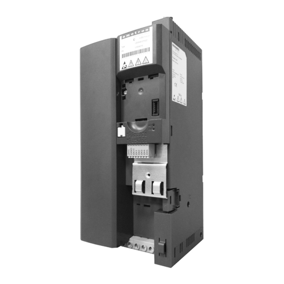
Product description Product description Mains connection X100 PE connection Relay output X9 Network X2xx Option Network status-LEDs DIP switch Baud rate and bus address (CANopen/Modbus PROFIBUS) Interface X16 Diagnostic module Inverter status LEDs Memory module X20 Control terminals X3 Standard I/O or Application I/O Shield connection Control connections Safety module X1... -
Page 8: Mounting
Mounting Important notes Mounting Important notes DANGER! Dangerous electrical voltage Possible consequence: death or severe injuries ▶ All works on the inverter must only be carried out in the deenergised state. ▶ After switching off the mains voltage, wait for at least 3 minutes before you start working. NOTICE! ▶... -
Page 9: Mechanical Installation
Mounting Mechanical installation Mechanical installation Dimensions 4 hp - 7.5 hp All Dimensions in inch... - Page 10 Mounting Mechanical installation Dimensions 10 hp All Dimensions in inch...
- Page 11 Mounting Mechanical installation This page is intentionally left blank...
-
Page 12: Electrical Installation
Mounting Electrical installation Important notes Electrical installation 4.3.1 Important notes WARNING! ▶ The integral solid state short circuit protection included in the inverter does not provide branch circuit protection. Branch circuit protection must be provided in accordance with the National Electrical Code and any additional local codes. ▶... -
Page 13: 3-Phase Mains Connection 480 V
Mounting Electrical installation 3-phase mains connection 480 V 4.3.2 3-phase mains connection 480 V WARNING! ▶ Suitable for use on a circuit capable of delivering not more than 5,000 rms symmetrical amperes, 480/277 V maximum. ▶ When protected by fuses rated as given in tables below. ▶... - Page 14 Mounting Electrical installation 3-phase mains connection 480 V The wiring diagram is valid for Emotron DSV35 inverters. Fig. 1: Wiring example Run/Stop Mains contactor Fuses Dashed line = options...
-
Page 15: Fusing And Terminal Data
Mounting Electrical installation 3-phase mains connection 480 V 4.3.2.1 Fusing and terminal data Inverter DSV35407P3 DSV35409P5 DSV3540013 DSV3540016 Cable installation in compliance with Operation without mains choke Fuse Characteristic all acc. to UL 248/CC all acc. to UL 248/J, T, R Max. -
Page 16: Canopen
Mounting Electrical installation Modbus 4.3.3 CANopen Typical topologies Line X216 X216 X216 X216 Terminal description CANopen Connection X216 Connection type Spring terminal Min. cable cross-section Max. cable cross-section Stripping length inch 0.39 Tightening torque lb-in Required tool 0.4 x 2.5 Basic network settings Use the DIP switch to set the node address and baud rate and to activate the integrated bus terminating resistor. -
Page 17: Modbus
Mounting Electrical installation CANopen 4.3.4 Modbus Typical topologies Line X216 X216 X216 X216 TB COM TB COM TB COM TB COM Terminal description Modbus Connection X216 Connection type Spring terminal Min. cable cross-section Max. cable cross-section Stripping length inch 0.39 Tightening torque lb-in Required tool... -
Page 18: Connection Of The Safety Module
Mounting Electrical installation Connection of the safety module 4.3.5 Connection of the safety module 4.3.5.1 Important notes DANGER! Improper installation of the safety engineering system can cause an uncontrolled starting action of the drives. Possible consequences: Death or severe injuries ▶... -
Page 19: Connection Plan
Mounting Electrical installation Connection of the safety module 4.3.5.2 Connection plan Passive sensors Active sensors safety switching device active sensor - example lightgrid passive sensor 4.3.5.3 Terminal data Terminal description Safety STO Connection Connection type Screw terminal Min. cable cross-section Max. -
Page 20: Commissioning
Mounting Electrical installation Connection of the safety module Commissioning Important notes WARNING! Incorrect settings during commissioning may cause unexpected and dangerous motor and system movements. Possible consequence: death, severe injuries or damage to property ▶ Clear hazardous area. ▶ Observe safety instructions and safety clearances. Before initial switch-on Prevent injury to persons and damage to property. -
Page 21: Initial Switch-On / Functional Test With Terminal Control
Commissioning Commissioning Initial switch-on / functional test with terminal control Important notes Initial switch-on / functional test with terminal control Target: achieve rotation of the motor connected to the inverter as quickly as possible. Requirements: • The connected motor matches the inverter in terms of power. •... - Page 22 Technical data Standards and operating conditions Carrying out the functional test 1. Start drive: 1. Start inverter: X3/DI1 = HIGH. a) If the inverter is equipped with an integrated safety system: X1/SIA = HIGH and X1/SIB = HIGH. 2. Activate preset frequency setpoint 1 (20 Hz) as speed setpoint: X3/DI4 = HIGH. The drive rotates with 20 Hz.
-
Page 23: Technical Data
Commissioning Initial switch-on / functional test with terminal control Technical data Standards and operating conditions Conformities 2014/35/EU Low-Voltage Directive 2014/30/EU EMC Directive (reference: CE-typical drive system) TR TC 004/2011 Eurasian conformity: safety of low voltage equipment TP TC 020/2011 Eurasian conformity: electromagnetic compatibility of technical means RoHS 2 2011/65/EU... - Page 24 Technical data 3-phase mains connection 480 V Standards and operating conditions Mains current > 16 A: with mains EN 61000-3-12 RSCE: short-circuit power ratio at the connection point choke or mains filter, with of the machine/plant to the public network. dimensioning for rated power.
-
Page 25: 3-Phase Mains Connection 480 V
Technical data 3-phase mains connection 480 V The output currents apply to these operating conditions: • At a switching frequency of 2 kHz or 4 kHz: Max. ambient temperature 113 °F. • At a switching frequency of 8 kHz or 16 kHz: Max. ambient temperature 104 °F. -
Page 26: Rated Data
Technical data 3-phase mains connection 480 V 3-phase mains connection 480 V Rated data 6.2.1 Rated data DSV35407P DSV35409P5 DSV3540013 DSV3540016 Inverter Rated power Mains voltage range 3/PE AC 340 V ... 528 V, 45 Hz ... 65 Hz Rated mains current without mains choke 10.5 14.3... - Page 27 Technical data...
- Page 28 © 03/2016 | 13502553 | 1.0 / 01-6407-01r1 CG DRIVES & AUTOMATION Mörsaregatan 12, Box 222 25 SE- 250 24 Helsingborg, Sweden +46 42 16 99 00 Info: info.se@cgglobal.com Order: order.se@cgglobal.com...
Need help?
Do you have a question about the Emotron DSV35 and is the answer not in the manual?
Questions and answers