Table of Contents

Summary of Contents for Groeneveld 4CH HD DVR
- Page 1 Operating Instructions 4CH HD DVR Thank you for using our Mobile DVR. Please read this User’s Manual carefully to ensure that you can use the device correctly and safely. The contents of this manual are subject to change without notice.
-
Page 3: Table Of Contents
Contents 1 Specifications................................1 2 Precautions................................3 3 Main Features................................. 4 4 Wiring Diagram............................... 6 5 Connection - Front Panel............................6 5.1 LED................................7 5.2 Electronic Lock............................7 5.3 Remote Controller............................8 5.4 SD Card Slot..............................9 6 Connection - Back Panel............................9 6.1 Power input (10-32V).......................... - Page 4 8.9 G-sensor Sensitivity..........................33 8.10 File Type..............................33 8.11 Record Audio............................34 9 Display..................................34 9.1 Camera Display Setting........................... 35 9.2 Camera Name Setting..........................35 9.3 System Language Setting........................36 9.4 Audio Out..............................36 9.5 OSD Display Setting..........................37 9.6 Menu on..............................37 9.7 Speed................................38 9.8 GPS................................39 9.9 Mirror................................
-
Page 5: Specifications
1 Specifications 4CH HD DVR Operating system Linux System Operating interface Graphical menu operation interface(OSD) Video permission Administrator & user setting Video input 4 x 1080P analog high definition CVBS output 1CH 6pin aviation connector output PAL/NSTC HDMI output 1CH HDMI output, 1080P... - Page 6 Wi-Fi hotspot/AP Optional Optional G-Sensor Three axis sensor Available /Gyroscope Windows client Available Software iOS client Available Web portal Available Input 10~32V Output 12V@3.5A Max Power Power Consumption Standby Power 100mW Consumption Operating temp. & -20℃~+70℃, RH80% Max. humidity Electrical spec Super Capacitor Available Clock...
-
Page 7: Precautions
2 Precautions 1) Motion detection function is set to OFF by default. Alarm files will be created when the motion detection is set ON. 2) G-Sensor recording is recommended to set ON during driving for emergency recording use. G-Sensor level is optional. 3) If the device could not boot up, try to remove all storage disks from the device, and then restart it to check whether it could boot normally or not. -
Page 8: Main Features
3 Main Features Controlled by touch screen All settings can be operated through the touch-control monitor. Video and Audio 4 channels x 1080p. 4 video inputs with audio. 2 video outputs with audio. 1 CVBS output (1 x 6 PIN OUT), 1 x HDMI(1080P). ... - Page 9 Support LAN, Wi-Fi, and 2G / 3G / 4G. LAN, Wi-Fi and 2G / 3G / 4G have the sequence priority of connections. They are automatically switched to save the data once LAN, Wi-Fi or 2G/3G/4G is connected. Recording files can be uploaded to the server.
-
Page 10: Wiring Diagram
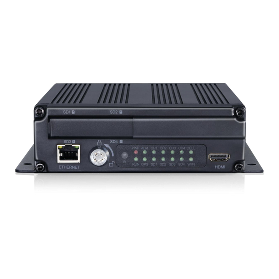
4 Wiring Diagram 5 Connection - Front Panel ① ② ③ ④ ⑤ ⑥ ① SD Card Slot ④ IR Receiver ② Ethernet(RJ45) ⑤ LED Indicators ⑥ HDMI output ③ Electronic lock... -
Page 11: Led
5.1 LED PWR: Red LED, lights up when DVR is powered on, and goes out when power is cut off. RUN: Keeps on when DVR is being launched and flashes when DVR is running. ALM: Alarm indicator. It keeps on with the record when there is Alarm-in, G-sensor activation or motion detection or speed or panic button event alarm. -
Page 12: Remote Controller
5.3 Remote Controller Use the remote controller closer enough to the IR Receiver, otherwise it may not work. DESCRIPTION Not in use POWER Switch the screen to channel 1~ 4 for live view. Switch to default display Call up main menu MENU Upward for MENU selection Towards to left for MENU selection or Menu... -
Page 13: Sd Card Slot
5.4 SD Card Slot SD card type: Each card Max. Capacity 128GB Insert, remove SD card Step 1: Use the key to unlock and open front plate Step 2: Insert SD card to SD card slot (the inserting way is shown as the picture below) Step 3: Close the front plate and use the key to lock 6 Connection - Back Panel ①... -
Page 14: Power Input (10-32V)
6.1 Power input (10-32V) Connection method Connect ignition wire to yellow ACC, battery Positive to V+ (Red wire) and Negative to GND (black wire). 6.2 Cameras (AVIN 1~4) Below is the definition of camera input (male). How to connect cameras Four cameras can be directly or via extension cable connected to the 4CH aerial ports on the DVR rear panel. -
Page 15: Lcd Monitor
6.3 LCD Monitor High definition monitors are recommended to work with the device as below: Output resolution of the LCD monitor can be selected. Settings are as follows: AUTO supports as below: System Format CVBS AUTO NTSC/PAL 1080P/720P... -
Page 16: Buzzer
6.4 Buzzer If the device is not connected to a monitor, please check the recording status by the buzzer. The buzzer would alarm if the device is not recording under Normal Mode which is set by default. To stop the buzzer from alarming, please make sure the device is working properly. The buzzer warning function is as follows: The buzzer will keep beeping for a while for all types of alarm event recording. - Page 17 1) There are 8 alarm inputs including alarm inputs 1 ~ 4, reversal input, brake input, turn left input, turn right input, which can trigger the alarm recording. The first 4 alarm inputs are normal alarm input defined by user. The last 4 are specific alarm input and display cursor for each channel. 2) Alarm output 1 and alarm output 2 are 12V by default, which can be used as a trigger and working together with alarm inputs.
-
Page 18: Panic Button And Its Conversion Cable (Optional)
6.6 Panic Button and Its Conversion Cable (Optional) Overview The LEDs are used to show the working status of the device. But when the device is installed in the vehicle, it is not easy to check the LED on the front panel. Each LED indicates the corresponding status of the device. - Page 19 Panic Button Panic Button is labeled as “Bookmark”. 1) When the bookmark button is pressed, an emergency event will be triggered. 2) When the bookmark button is pressed, the Event LED light will work temporarily. If the panic button alarm recording cannot be triggered, please check if the Event Rec. is set ON as shown below: If the alarm recording was triggered, there will be an alarm sign on the screen, as shown below: IR receiver...
-
Page 20: Four-In-One Antenna (Gps, 2G/3G/4G, Wi-Fi)
The Buzzer The alarm from the buzzer in panic button is convenient for checking the status of the device. No matter the Buzzer is set as ON or OFF in the menu System->Exception, the buzzer will alarm for 4 seconds when the DVR is booted up and when the panic button is hot plugged. - Page 21 System time display ① License plate number display ② ③ Recording status The recording sign will turn red when recording starts. Playback ④ The playback icon will turn red during playing back. ⑤ Electronic lock Lock indicator turns red when it is locked and the front cover is closed. ...
-
Page 22: Menu Lock
7.2 Menu Lock The device/recorder supports two kinds of permissions: admin permission and guest permission. Users’ account list Admin Permission Guest Permission User Name admin guest Password Modification Initial Password Enter the menu of Enter all menus Playback, Display mode Permission switching and Volume Users’... - Page 23 Only the administrator could change the status of Menu lock. The following picture shows how to change the Menu Lock status from ON to OFF. When the menu lock status is "ON", you need to enter the user name “admin” and password to ...
-
Page 24: Keyboard Operation Instruction
7.3 Keyboard Operation Instruction : Switch letter case :Exit the keyboard interface :Delete the input letters :Switch to the numeric interface :Switch to the English alphabet interface :Switch to the special character interface... - Page 25 Character Switching Introduction...
-
Page 26: Manual Recording
Letter Case Switching Introduction 7.4 Manual Recording Touch this icon to start or stop recording. -
Page 27: Playback
7.5 Playback Video Playback button: Touch this icon to enter the calendar menu. Green marked date means it has recording files saved on that day. Select the date to enter the video file list, then select the file and touch Play icon to play video. You can select single or multiple videos at a time. - Page 28 Event: Alarm recording list, including alarm recording 1~8, motion detection recording, G-sensor recording, over-speed recording and panic button recording. Type Recording Time Control Mode View Position Normal recording Manual control Normal list Power on recording Manual control Normal list Schedule recording Pre-setup time Normal list Alarm recording 1~8...
- Page 29 The abbreviations of record types are as following: Play Interface Normal recording Scheduled Recording Motion detection recording Over speed recording Temperature recording Panic button recording Alarm 1 recording Alarm 2 recording Alarm 3 recording Alarm 4 recording Reverse recording Brake recording Left recording Right recording...
-
Page 30: Log
7.6 Log System Log checking, Log export. 7.7 Display Mode Switching Display mode switch: Press the icon to display 12 types of mode. The default mode is quad view. Display mode selection. ① ② Touch the icon to set up the default. Exit. -
Page 31: System
7.8 System System Settings: Touch the icon to enter the setup menu. A window warning will pop up "Unable to record in set-up mode! Continue?”, touch OK to enter. 7.9 Disk Disk Management Icon: Touch the icon, then you can view the status of SD card and USB storage as below. -
Page 32: Volume
If ALL shows 0.00MB, it means that DVR does not have access to this type of disk. ③ Green shows the capacity of all the recording files in the Normal list, Red shows the capacity of all the recording files in the Event list, Blue shows the capacity of all the pictures in the Capture list, Yellow shows the capacity of all the other files except those above, Grey shows the capacity which is not used. -
Page 33: Record Setup
8 Record Setup 8.1 Power On Rec When “Power On Rec” is set to ON, the device will start recording once it’s powered on. Default setting is ON. 8.2 Cyclic Rec When “Cyclic Rec” is set to ON, new recording files will overwrite the previous ones when the disk is full. -
Page 34: Video Quality
Event Rec.: Event recording refers to the alarm recording triggered by events including motion detection, G-force, alarm 1 ~ 6, panic button and over speed. If the Event Rec is set to ON and corresponding alarm parameters are set, event recording will be activated when the events above are triggered. If the Event Rec is set to OFF, event recording will not be activated even if an alarm is triggered. - Page 35 There are 5 kinds of optional resolution in main stream menu, 1080P, 720P, D1 (PAL), D1 (NTSC) and AUTO. And there are 3 kinds of optional resolution in sub stream menu, CIF (PAL), CIF (NTSC) and AUTO. For higher resolution and better video quality, the video file will be larger. Therefore, the file size should be taken into consideration during configuration.
-
Page 36: Record Channel
SD capacity Video Quality File length 4 x 1080P, 4Mbps ≈76h 4 x 720P, 2Mbps ≈152h 4 x D1, 1Mbps ≈304h 4 x 128GB 1 x 1080P, 4Mbps ≈304h 1 x 720P, 2Mbps ≈608h 1 x D1, 1Mbps ≈1216h 8.5 Record Channel The default configuration is shown above. -
Page 37: File Length
8.7 File Length The default video file length in AVI and MSV format is 5 min. AVI format video file length can be set to 5 minutes, 10 minutes, 15 minutes. The length of the video file in MSV format can be set to 2 minutes, 3 minutes, 5 minutes. File Format File Length 5min,10min,15min... -
Page 38: Record Audio
8.11 Record Audio Set the recording audio of the channel. When the recording channel is selected, the audio of the channel will be recorded in the recording file. If this channel is not selected, there is no audio in the recording of this channel. -
Page 39: Camera Display Setting
9.1 Camera Display Setting Camera parameter setting for each corresponding channel includes brightness, contrast, saturation and hue. All default settings are 50. To change the value, drag the bar to left or right to decrease or increase. 9.2 Camera Name Setting Camera names are displayed at the bottom of each channel. -
Page 40: System Language Setting
9.3 System Language Setting English and Russian are available in the menu for your options. The default language is English. 9.4 Audio Out Select the audio output channel in multi-display mode. The default configuration is shown below. -
Page 41: Osd Display Setting
9.5 OSD Display Setting Time, Camera name and License number can be selected whether to display or not. If it is on, the information will be shown in the live and the playback video. The default configuration is shown below. 9.6 Menu on Set the menu display duration. -
Page 42: Speed
Menu On: Duration can be set to 30s, 60s, 120s and Always. When it is set to 30s, 60s, 120s, it means that the menu will disappear if there is no operation in 30s, 60s or 120s. When it is set to Always, the menu will always be there. -
Page 43: Gps
9.8 GPS When the GPS antenna is properly installed, the latitude, longitude and speed will be recorded. The menu provides the GPS information including latitude, longitude, detectable satellites, and accessible satellites etc. Mode: indicates the GPS connection status. Used: indicates the number of available satellites. Visible: indicates the number of searchable satellites. -
Page 44: System Format Setting
Vertical: when it is set to ON, the corresponding recording channel will flip vertically; when it is set to OFF, no vertical flip will be done. The setting steps are show as follows: 9.10 System Format Setting The default configuration is shown above. CVBS: Standard definition display HD: HD display Correct: When the interface displayed on the display screen is not complete, the display interface can be... -
Page 45: Network
reduced. Each unit of reduction is two pixels, and the maximum can be reduced by 64 units. When the interface is reduced, the DVR can only be operated by the remote control. 10 Network 10.1 LAN and Server Setting... - Page 46 The default configuration is shown above. DHCP: Dynamic Host Configuration Protocol. Set on for dynamic IP and off for static IP. Static IP must be manually input with IP address, mask and gateway. MAC address can be automatically assigned or revised. LAN connection ...
-
Page 47: Wi-Fi Network Setup And Server Setup
10.2 Wi-Fi Network Setup and Server Setup The default configuration is shown above. Wi-Fi: ON/OFF DHCP: Dynamic Host Configuration Protocol. Set On for dynamic IP and Off for static IP. Static IP must be manually input with IP address, mask and gateway. SSID: Wi-Fi hotspot list. - Page 48 Step 4: Touch SSID sub-menu to select the hotspot and input the password. Step 5: Touch OK to exit. Step 6: Go to “Network -> Server” page to input Wi-Fi Server IP and Port. Touch OK to save the settings. Step 7: Wi-Fi network status and server status can be checked on “Network - >Status”.
-
Page 49: 3G/4G Control And Setup
10.3 2G/3G/4G Control and Setup The default configuration is shown above. Cellular: Cellular is on, meaning that 2G/3G/4G is on. Standard: WCDMA is set by default. APN & Access No.: Normally, the user doesn’t need to input user name and password for APN and Access number, the default setting is available. -
Page 50: Ap Internet Setup
Step 6: Touch OK to exit. Step 7: Input the 2G/3G/4G Server IP and Port on “Network->Server”. Step 8: Cellular network status and server status can be checked on “Network - >Status”. 10.4 AP Internet Setup Steps to connect AP Internet ... - Page 51 LAN IP: The static IP set on “Network->LAN” page or the dynamic IP obtained automatically. MAC: The static physical address set on Network-LAN page or the dynamic physical address obtained automatically. Wi-Fi: Status indication. Wi-Fi RSSI: Wi-Fi signal strength indication. Wi-Fi IP: Static IP obtained from Network-Wi-Fi page or dynamic IP address.
-
Page 52: Server
10.6 Server The function of server setting is mentioned in Chapter 10.1, 10.2 and 10.3..The default server IP of LAN, Wi-Fi and Cellular are “183.233.190.23”, and the default port number is “9090”. 10.7 File Upload “Upload Files” default configuration as shown above. Upload Files:ON/OFF Normal File:Two states, “OFF”... - Page 53 OFF:Upload other videos besides normal ones: event recording files, scheduled recording files ON:Upload all video files (Including normal video) Cellular:Two states, “OFF” and “ON”. OFF: When using Cellular to connect to the server, uploading files is not allowed. For example, the following figure shows that the recording file will only be uploaded when using LAN or Wi-Fi to connect to the server.
-
Page 54: System
11 System... -
Page 55: Log In Setup
11.1 Log in Setup Set user name and password for booting up. The initial password is 123. 11.2 License Plate Number Setup Input license plate number. The default configuration is shown below. -
Page 56: System Time Setup
11.3 System Time Setup Format Setup: "Format" default configuration as shown above. Go to “System – >Date &Time - >Format->Setup” page. Time Zone: Time zone setting. ① Date Format: Set the date of format. ② 24 Hour: If it is ON, time format will be displayed in 24-hour system. If OFF, time format will be ③... - Page 57 Time Sync Setup: "Time Sync" default configuration as shown above. Go to “System -> Date &Time ->Time Sync->Setup” page. GPS: Set GPS to ON/OFF. ① NTP: Set NTP to ON/OFF. ② NTP Server: Show the URL of the NTP Server. ③...
-
Page 58: Scheduled Recording
11.4 Scheduled Recording The default configuration is shown above. Enable: Set scheduled recording ON/OFF. Start: Set start time of scheduled recording. End: Set end time of scheduled recording. Weekday: Set scheduled recording by weekdays. Select the weekdays to set preset. Scheduled Recording: Support up to four appointed tasks. -
Page 59: Exception
11.5 Exception The default configuration is shown above. Exception Buzzer: Set the exception buzzer to ON/OFF. Duration: Set the duration time of the buzzer. 11.6 ACC Settings... -
Page 60: Alarm Information Setting
The default configuration of "Shutdown Voltage" and "ACC Duration" is shown above. Current voltage: Voltage of the working DVR. Shutdown voltage: When the current or voltage is lower than the shutdown voltage, the device will shut down automatically. When the current or voltage is higher than the shutdown voltage, the device would work properly. - Page 61 When different types of alarm are triggered at the same time, alarms with the highest priority will work first. “Alarm 1” default configuration as shown above Trigger Level: There are 3 options of Trigger Level. The options “Low” and “High” are used for turning on alarm function.
- Page 62 Line selecting: There are five lines to be selected. Line U (up), Line D (down), Line L (left), Line R ③ (right) and ALL. The button turns green if selected. You can use remote control to operate. There are four directions to adjust the shape of the cursor, Up, Down, Left and Right. ④...
-
Page 63: Update
11.8 Update For single device Step 1: Copy the folder to USB disk or SD card root directory and insert the USB disk or SD card into the device. Step 2: Power off the DVR and reboot it, then it will upgrade automatically. Or go to Menu -> System -> Update->Software;... - Page 64 Step 3: When “Update success!” is shown on the display, the device will reboot automatically. Step 4: After rebooting, please check if the version is the same as the one you copy into “upgrade” folder. Please go to Menu -> System -> Info to check it. Note: After the upgrade is complete, the "dvxxx_upgrade_201xxxxxxxxx_Rename"...
-
Page 65: Configuration
Logo upgrade 1) Put four logo pictures into the root directory of SD card or USB flash drive; 2) Insert the SD card or the USB flash drive into the DVR device, click System->Update->Logo, and then click OK. Then there will be a prompt message that “start to update the Logo, please wait...”. When the update is finished successfully, a prompt message that “Logo update successfully, restart DVR now?”... -
Page 66: System Info
Configuration Export: Export Log to SD card or USB memory flash devices. Factory Default: Press Reset to restore factory settings. 11.10 System Info System Info:Software version number. -
Page 67: Faq
12 FAQ 1) The System Can’t Start up? Check the power connection. Please follow the steps below to check the power connection: Check the input power: if the power wire is connected correctly, if the ground wire is connected to ①... -
Page 68: Appendix
13 APPENDIX APPENDIXⅠ: Abbreviation & Description Daylight Saving Time Rec. Record G-sensor Accelerometer sensor Secure Digital Memory Card Global Positioning System Universal Serial Bus Wi-Fi Wireless-Fidelity Alarm Camera VLOSS Video Loss Audio Video Interleaved COMM Communication On-Screen Display Error Access Point Name Memory Dynamic Host Configuration DHCP... -
Page 69: Appendixⅱ: Accessories
APPENDIXⅡ: Accessories Standard Table: Accessories Quantity Description Accessories Quantity Description Remote Power Cable Control RS232,RS48 4CH HD DVR Key 5 cable 6p to 4p Four-in-one Antenna conversion (GPS, 2G/3G/4G, cable, Wi-Fi) supplied Alarm, speed sensor, temperature sensor connecting cable Optional Accessories Table:... -
Page 70: Appendix Ⅲ: Compatibility Storage List
APPENDIX Ⅲ: Compatibility Storage List SD Card Name Describtion 32GB SD Card 32G, MLC,NCSXDAB-032G,Longsys,-25 ℃~85℃ 64GB SD Card 64G, MLC,NCSXJAB-064G ,Longsys,-25 ℃~85℃ 128GB SD Card 128G, MLC,NCSXJAB-128G ,Longsys,-25 ℃~85℃ 64GB micro SD Card 64G,MLC,NCIXJBB-064G...
Need help?
Do you have a question about the 4CH HD DVR and is the answer not in the manual?
Questions and answers