Table of Contents
Advertisement
Quick Links
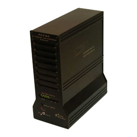
PZ3 Low Impedance Amplifier
PZ3 Overview
The PZ3 is a high channel count, low
impedance amplifier well suited for ECOG,
Evoked Potentials, EEGs, LFP's, EMGs, and
other similar recording applications. Available in
32, 64, and 128 channel models, the PZ3
amplifier offers shared or true differential
operation, low input referred noise, impedance
checking, and an optional high input range
mode.
System Hardware
A standard configuration for low sample rate,
low impedance recordings includes 1.5 mm
TouchProof connectors for electrodes, a PZ3
amplifier, and an RZ2 base station.
The battery powered PZ3 digitizes and amplifies
signals recorded from each of the electrode
channels. All digitized signals are sent via a
single fiber optic connection to the RZ2 base
station for further processing. The RZ2 also sends amplifier configuration information
to the PZ3 across the fiber optics.
The diagram below illustrates this flow of data and control information through the
system.
PZ3 Data and Control Flow Diagram
7-65
PZ3 Low Impedance Amplifier
Advertisement
Table of Contents

Summary of Contents for Tucker-Davis Technologies PZ3
- Page 1 7-65 PZ3 Low Impedance Amplifier PZ3 Overview The PZ3 is a high channel count, low impedance amplifier well suited for ECOG, Evoked Potentials, EEGs, LFP’s, EMGs, and other similar recording applications. Available in 32, 64, and 128 channel models, the PZ3 amplifier offers shared or true differential...
-
Page 2: Recording Modes
For Shared Differential operation, each bank of channels uses a separate shared reference. Shared Differential, Bank 1 and 2 Functional Diagram The PZ3’s impedance checking and a high voltage range features can be used in both true and shared differential modes. It is also important to note that in the various modes of operation, the RZ2 processor may use the alternate channels to report information such as impedance values or RMS. -
Page 3: Hardware Setup
System 3 7-67 connectors on the PZ3 back panel. A break out box or connector(s) are required for electrode connection. TDT provides a version of our LI-CONN connector for the PZ3: the LI-CONN-Z for Shared Differential mode. It features standard 1.5 mm safety connectors and provides easy connections between electrodes and the amplifier. - Page 4 For Example: If you are using a PZ3 with 128 channels, powering down Bank A (Select Yes) would power down the first four blocks of 8 channels of the PZ3, disabling channels 1 –...
- Page 5 A CoreSweepControl macro is included to handle the required timing functions used by programs such as OpenEx and a PZ3_Control macro configures the operation mode of the PZ3 as well as any additional options that may be necessary. Three PZ3 Low Impedance Amplifier...
-
Page 6: Powering Off
PZ3 Operation RCX control circuits running on the base station must include PZ3 specific macros to configure the amplifier’s mode of operation; Shared Differential or Individual Differential and other configuration options such as input range and clip warning display. “PZ3 Software Control”... - Page 7 TDT hardware removes this ground loop at the cost of raising the overall noise floor a small amount. A banana jack located on the back of the PZ3 (directly to the right of the charger input) provides connections to common ground for the first bank of channels (1- 16).
-
Page 8: Battery Overview
15kW) specified by the user (set using the PZ3_Control macro). The LEDs on the PZ3 (and in the PZ3 display on the RZ2 LCD) will light green when the electrode impedance is less than or equal to the target impedance or red when electrode impedance is greater than the target impedance value. -
Page 9: Charging The Batteries
Eight LEDs indicate the voltage level of the selected battery bank. These LEDs can be found on the front of the PZ3 amplifier by the heading Level. When the battery is fully charged, all eight LEDs will be lit. When the battery voltage is low, only one green LED will be lit. - Page 10 Please note that this does not necessarily reflect how the hardware channels are used on the PZ3. The RZ2 interprets input from the PZ3 then makes the data available as described below. To further simplify circuit design, the PZ3_ChanMap macro can be used to build separate multichannel data streams for waveform data and impedance values.
- Page 11 Up to 128 status or clip warning, battery life, active battery bank Indicator LEDs See figures below Input referred noise 5 meters standard, cable lengths up to 20 meters* Fiber Optic Cable *Note: If longer cable lengths are required, contact TDT. PZ3 Low Impedance Amplifier...
-
Page 12: Input Connectors
7-76 System 3 Input Connectors PZ3 amplifiers have up to 16 26-pin headstage connectors on the back of the unit. The PZ3 channels are marked next to the respective connector on the amplifier. Pinout Diagram Note: There are 8 (+) channels and 8 (-) channels per DB26 connector. Subsequent banks are indexed by an additional 8 channels.
Need help?
Do you have a question about the PZ3 and is the answer not in the manual?
Questions and answers