Table of Contents
Advertisement
Quick Links
Eco-Line Signal Converters User Manual
The Eco-Line range of signal converters has been designed using a low-cost, powerful microprocessor
which enables us to offer flexibility, reliability and accuracy at a really good price in a small package.
If you have any comments or suggestions which could improve this User Manual please e-mail them to me
at
mailto:miked@danntech.com?subject=Eco-Line User Manual -
Configuration ................................................. 2
How it Works ................................................. 4
Quick Configuration Guide ............................ 5
Button Link .................................................... 8
Input Range Selection ................................... 9
Input Setup: ................................................... 9
Output Range Selection .............................. 10
Output Setup ............................................... 10
Test Mode ................................................... 12
DIP SW1 Operational Settings .................... 14
Power Up .................................................... 16
Application Examples .................................. 16
Danntech makes no warranty of any kind with regard to this material, including, but not limited to, the implied warranties of merchantability and fitness for a particular
purpose. Danntech shall not be liable for errors contained herein or for incidental or consequential damages in connection with the furnishing, performance or use of this
material. This document contains proprietary information, which is protected by copyright. No part of this document may be photocopied, reproduced, or translated into
another language without the prior written consent of Danntech. The information in this document is subject to change without notice.
Filename: Eco-Line_Signal_Converters_User_Manual.docx
Version: 1.17
©
danntech
- PROCESS INSTRUMENTATION
Using miniature DIP switches, a variety of standard inputs and outputs can be
selected and with the 'one button' calibration, accurate operation in any
configuration is assured. Having selected the required input and output ranges,
these can be adjusted to be anything within the selected range using the 'one
button' calibration.
For example, with a 0 to 100 mV input and ±10V
output selected, one can calibrate the device to
have say 0 to 60 mV input where 30 mV input gives
an output of 0 V, 60 mV an output of +6 V and for
0 mV input and output of - 6 V. Output inversion is
also easily accommodated.
The Zero and Span trimpots can be disabled or switched to a wider adjustment
range using the DIP switches. Filtering is also DIP switch selectable in four ranges
up to 60 seconds.
We can also make firmware changes if you have a special application that we have
not catered for.
Comment.
Typical Results ........................................... 16
Other Eco-Line Versions ............................. 17
Preset Signal Source .................................. 17
Serial Communications ............................... 17
................................................................... 18
Opening the Enclosure ............................... 19
Line Signal Converters ............................... 20
Specifications ............................................. 21
Part Numbering .......................................... 22
danntech
©
2020
www.danntech.com
www.danntech.co.za
www.danntech.biz
02 May 2020
Page 1 of 22
Advertisement
Table of Contents

Related Manuals for Danntech Eco-Line GB-SE/IA-IA/C

Summary of Contents for Danntech Eco-Line GB-SE/IA-IA/C
-
Page 1: Table Of Contents
Danntech makes no warranty of any kind with regard to this material, including, but not limited to, the implied warranties of merchantability and fitness for a particular purpose. Danntech shall not be liable for errors contained herein or for incidental or consequential damages in connection with the furnishing, performance or use of this material. -
Page 2: Configuration
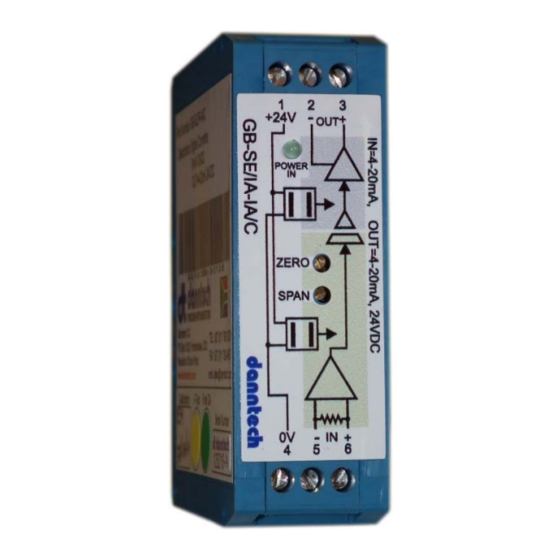
Outputs: 0-100mV, 0-1V, 0-10V, ±10 V, 0 to 22 mA The User Configurable Version provides a way to configure the device for non-standard inputs and Filename: Eco-Line_Signal_Converters_User_Manual.docx 02 May 2020 Version: 1.17 © danntech Page 2 of 22 – PROCESS INSTRUMENTATION... - Page 3 The DIP switches, Push Button Link and setup LEDs are accessed by removing the covering stickers. Filename: Eco-Line_Signal_Converters_User_Manual.docx 02 May 2020 Version: 1.17 © danntech Page 3 of 22 – PROCESS INSTRUMENTATION...
-
Page 4: How It Works
We have also included an optional, isolated RS232/TTL interface which will be used in later versions for configuration purposes, data logging and is able to be used for CANBUS. Filename: Eco-Line_Signal_Converters_User_Manual.docx 02 May 2020 Version: 1.17 © danntech Page 4 of 22 – PROCESS INSTRUMENTATION... -
Page 5: Quick Configuration Guide
The filtering you desire (using SW1 switches 3 and 4 – switch 4 ON and 3 OFF = 1 second, for other selections see the table). Filename: Eco-Line_Signal_Converters_User_Manual.docx 02 May 2020 Version: 1.17 © danntech Page 5 of 22 – PROCESS INSTRUMENTATION... - Page 6 PB link next to DIP switch SW1). Hold in the Push Button until the Red Configuration LED comes on. 5. The Green Configuration LED (as well as the Status LED) will come on for about 1 second Filename: Eco-Line_Signal_Converters_User_Manual.docx 02 May 2020 Version: 1.17 © danntech Page 6 of 22 – PROCESS INSTRUMENTATION...
- Page 7 Zero and Span trimpots to give the exact outputs you require. Do this once to set and a second time to check – for best accuracy. Filename: Eco-Line_Signal_Converters_User_Manual.docx 02 May 2020 Version: 1.17 © danntech Page 7 of 22 – PROCESS INSTRUMENTATION...
-
Page 8: Dip Switches Push Button (Pb) And Push Button Link
DIP Switches Push Button (PB) and Push Button Link Filename: Eco-Line_Signal_Converters_User_Manual.docx 02 May 2020 Version: 1.17 © danntech Page 8 of 22 – PROCESS INSTRUMENTATION... -
Page 9: Input Range Selection
Release the Push Button as the red LED flashes, this latches the input value as the maximum input calibration value. The green LED will now flash as follows: Filename: Eco-Line_Signal_Converters_User_Manual.docx 02 May 2020 Version: 1.17 © danntech Page 9 of 22 – PROCESS INSTRUMENTATION... -
Page 10: Output Range Selection
To see the internal values you must have this link installed. Typically the info displayed will be: Eco-line Signal Converter - (dt331) Copyright Danntech 2012 Firmware V200 Input Cal Mode. Use Button to capture Input Minimum and Input Maximum Ain=2955 VR1=3727 VR2= 857 SW1= 24 Button=0 m=1.06 c=580.20 DACOut=3737... - Page 11 Typically the info displayed will be: Eco-line Signal Converter - (dt331) Copyright Danntech 2012 Firmware V200 Output Cal Mode. Use Button to capture Output Min and Max. <SW1-6 OFF=Ain, ON=POTs top=zero, bot=span> Ain= 535 VR1=3727 VR2= 857 SW1=104 Button=0 m=1.07 c=285.11 DACOut= 857 [Your unit may not have the COMMS jack socket fitted] Filename: Eco-Line_Signal_Converters_User_Manual.docx...
-
Page 12: Test Mode
Zero and Span adjustments. The green LED will flash as follows: First press – output = zero Second press – output = calibrated minimum Filename: Eco-Line_Signal_Converters_User_Manual.docx 02 May 2020 Version: 1.17 © danntech Page 12 of 22 – PROCESS INSTRUMENTATION... - Page 13 (the unit is shipped with this link out). Typically the info displayed will be: Eco-line Signal Converter - (dt331) Copyright Danntech 2012 Firmware V200 Use Button to Cycle through outputs => 0, min, (max-min)/2, max 4095 Ain= 536 VR1=3727 VR2= 858 SW1=136 Button=0 m=1.07 c=285.11 DACOut= 859 Tm=1.00 Tc=0.00 Runtime= 122...
-
Page 14: Dip Sw1 Operational Settings
Inject Maximum Input Value – press and hold button until green LED stops flashing and stays on, then release button. Output Calibration Activation Source Select OFF = Input is selected as the output activation source. Filename: Eco-Line_Signal_Converters_User_Manual.docx 02 May 2020 Version: 1.17 © danntech Page 14 of 22 – PROCESS INSTRUMENTATION... - Page 15 7. then back to following the input – step 1. Using the calibrate button you can cycle through these outputs. The cycle is repeated as the button is pressed. Filename: Eco-Line_Signal_Converters_User_Manual.docx 02 May 2020 Version: 1.17 © danntech Page 15 of 22 – PROCESS INSTRUMENTATION...
-
Page 16: Power Up
All the LEDs flash twice on power up or when the unit resets for any reason. On power up the following is sent to the RS232 port irrespective of the CN2 link. Eco-line Signal Converter - (dt331) Copyright Danntech 2012 Firmware V200 Normal power up! -
Page 17: Other Eco-Line Versions
RS232 TTL using the 4 way jack socket. This will be used in the future to provide a software configuration feature. We can also provide a configuration cable which provides connection from USB to our RS232 TTL. Filename: Eco-Line_Signal_Converters_User_Manual.docx 02 May 2020 Version: 1.17 © danntech Page 17 of 22 – PROCESS INSTRUMENTATION... -
Page 18: Setting Up Without A Process Signal Calibrator
When you have set up the input, you need to go back and configure the output to be what you required. This avoids the need for an expensive process signal calibrator for basic input types/ranges. Filename: Eco-Line_Signal_Converters_User_Manual.docx 02 May 2020 Version: 1.17 © danntech Page 18 of 22 – PROCESS INSTRUMENTATION... -
Page 19: Opening The Enclosure
Gently pry the left side cover apart from the label. front panel. Using the screwdriver gently pry open the enclosure all around taking care not to damage the plastic parts Filename: Eco-Line_Signal_Converters_User_Manual.docx 02 May 2020 Version: 1.17 © danntech Page 19 of 22 – PROCESS INSTRUMENTATION... -
Page 20: Some Other Interesting Things About The Eco-Line Signal Converters
If you squeeze the enclosure (front to back) you can press in the Push Button. So you can get away from using a sharp thin object to press in the switch. -
Page 21: Specifications
14. DIN rail mounting with flame proof high quality enclosure. 15. Screw terminal connections for wire diameter 2.5 mm 16. Dimensions 25 x 80 x 85 mm (W x H x D). Filename: Eco-Line_Signal_Converters_User_Manual.docx 02 May 2020 Version: 1.17 © danntech Page 21 of 22 – PROCESS INSTRUMENTATION... -
Page 22: Part Numbering
Supplied at 4-20mA/4-20mA setup. Uses push button and DIP switches to select various options. User can change settings and has overstickers for various options and blanks for user to make up own ranges. danntech cc Reg. No. CK1986/15338/23 Tel International: +27 11 7921239...
Need help?
Do you have a question about the Eco-Line GB-SE/IA-IA/C and is the answer not in the manual?
Questions and answers