Table of Contents
Advertisement
Quick Links
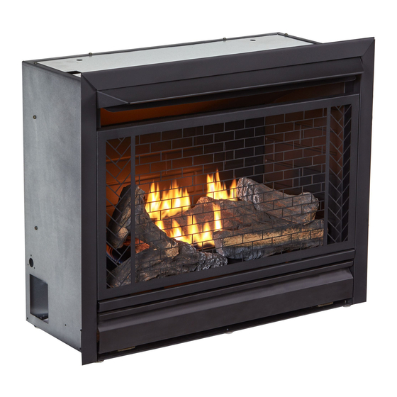
VENT-FREE GAS FIREPLACE
INSERT
OWNER'S OPERATION AND
INSTALLATION MANUAL
REMOTE CONTROLLED
MODELS
B300RTN
B300RTP
This insert can be used in the mantel and
fireplace systems CM300-1
WARNING: If the information in this manual is not
followed exactly, a fire or explosion may result causing
property damage, personal injury or loss of life.
— Do not store or use gasoline or other flammable va-
pors and liquids in the vicinity of this or any other
appliance.
— WHAT TO DO IF YOU SMELL GAS
• Do not try to light any appliance.
• Do not touch any electrical switch; do not use any
phone in your building.
• Immediately call your gas supplier from a neighbor's
phone. Follow the gas supplier's instructions.
• If you cannot reach your gas supplier, call the fire
department.
— Installation and service must be performed by a quali-
fied installer, service agency or the gas supplier.
WARNING: This appliance is only for use with the type
of gas indicated on the rating plate. This appliance is
not convertible for use with other gases.
Questions, problems, missing parts? Before returning to your retailer, call
our customer service department at 1-866-762-4050, 8:00 am - 4:30 pm CST,
(SKU:170268)
(SKU:170269)
Monday through Friday or email contact@bluegrassliving.com
CSA/ANS
Z21.11.2 2019
Unvented
Room Heaters
Advertisement
Table of Contents

Summary of Contents for BLUEGRASS B300RTN
- Page 1 Room Heaters VENT-FREE GAS FIREPLACE INSERT OWNER’S OPERATION AND INSTALLATION MANUAL REMOTE CONTROLLED MODELS B300RTN (SKU:170268) B300RTP (SKU:170269) This insert can be used in the mantel and fireplace systems CM300-1 WARNING: If the information in this manual is not followed exactly, a fire or explosion may result causing property damage, personal injury or loss of life.
-
Page 2: Table Of Contents
TABLE OF CONTENTS Safety ............3 Operation ..........17 Specifications ..........5 Inspecting Burners........21 Product Features ........5 Care And Maintenance ......22 Local Codes..........5 Electrical ..........24 Qualified Installing Agency ......6 Troubleshooting ........26 Unpacking..........6 Service Hints ........... -
Page 3: Safety
SAFETY IMPORTANT: Read this owner’s WARNING: Do not allow fans manual carefully and completely to blow directly into fireplace. before trying to assemble, op- Avoid any drafts that alter burner erate, or service this heater. flame patterns. Improper use of this heater can WARNING: Do not use a cause serious injury or death blower insert, heat exchange... - Page 4 SAFETY person should service and repair heater. WARNING: The fire screen or 11. Operating heater above elevations of guard designed for this unvent- 4,500 feet could cause pilot outage. ed appliance must be installed 12. To prevent performance problems, do not prior to operation.
-
Page 5: Specifications
SPECIFICATIONS B300RTN B300RTP Gas Type Natural Gas Propane Gas Ignition Piezo Ignitor Piezo Ignitor Input Rating 26,000 Btu/Hr 26,000 Btu/Hr Pressure Regulator Setting 3" W.C. 8" W.C. Maximum 10.5" Maximum 14" Inlet Gas Pressure* (inches of water) (*for purposes of input adjustment) Minimum 4"... -
Page 6: Qualified Installing Agency
UNPACKING 1. Remove top inner pack. 7. Remove log set by cutting plastic ties. 2. Tilt carton so that heater is upright. 8. Carefully unwrap log. 3. Remove protective side packaging. 9. Check for any shipping damage. If heater 4. Slide heater out of carton. or log is damaged, promptly inform your Remove protective plastic wrap. -
Page 7: Air For Combustion And Ventilation
AIR FOR COMBUSTION AND VENTILATION WARNING: If the area in which WARNING: This heater shall the heater may be operated does not be installed in a confined not meet the required volume for space or unusually tight con- indoor combustion air, combus- struction unless provisions are tion and ventilation air shall be provided for adequate combus-... -
Page 8: Installation
AIR FOR COMBUSTION AND VENTILATION Ventilation Air From Outdoors adjoining unconfined space. The combined Provide extra fresh air by using ventilation spaces must have enough fresh air to supply grills or ducts. You must provide two perma- all appliances in both spaces. nent openings: one within 12"... - Page 9 INSTALLATION CONNECTING ELECTRICAL Back of SUPPLY Fireplace Power This fireplace insert requires an 120V electri- Insert Change cal outlet within 4 feet of the unit. There is a Assembly power supply for the remote receiver located in the bottom of the fireplace insert. Exten- sions cords may be used.
- Page 10 INSTALLATION BUILT-IN FIREPLACE INSTALLATION WARNING: Do not allow any combustible materials to overlap the firebox front. WARNING: Do not allow combustible or noncombustible 3/4" Clearance to Facia materials to cover any necessary " Clearance to Sides, Back and Top openings like louvered slots. "...
- Page 11 INSTALLATION 3. Attach gas line to fireplace gas regulator. See Connecting to Gas Supply, page 14. 4. Check all gas connections for leaks. See Checking Gas Connections, page 16. IMPORTANT: When finishing your firebox, combustible materials such as wall board, gypsum board, sheet rock, drywall, plywood, etc, must have 1/2"...
- Page 12 INSTALLATION CONNECTING TO GAS SUPPLY WARNING: A qualified ser- CAUTION: Use pipe joint vice technician must connect sealant that is resistant to gas heater to gas supply. Follow all (Propane or Natural Gas). local codes. Before installing heater, make sure you have the items listed below: WARNING: This appliance •...
- Page 13 INSTALLATION Pointing the vent down protects it from freez- Place sediment trap where trapped matter is ing rain or sleet. not likely to freeze. A sediment trap traps mois- ture and contaminants. This keeps them from Install sediment trap in supply line as shown going into heater controls.
- Page 14 INSTALLATION CHECKING GAS CONNECTIONS Test Pressures Equal To or Less Than WARNING: Test all gas piping 1/2 PSIG (3.5 kPa) and connections for leaks after 1. Close equipment shutoff valve (see Fig- installing or servicing. Correct ure 16). all leaks at once. 2.
- Page 15 INSTALLATION 4. Check all joints from equipment shutoff 6. Light heater (see Lighting Instructions on valve to control valve (see Figure 17 or page 19). Check all other internal joints 18, page 16). Apply a noncorrosive leak for leaks. detection fluid to all joints. Bubbles form- 7.
- Page 16 INSTALLATION INSTALLING BATTERIES Receiver and Remote Control CAUTION: Do not mix old and Batteries are required in both the Remote new batteries. Do not mix alka- Control (Transmitter) (2 AAA size) and Re- line, standard (carbon - zinc), or ceiver (4 AA size) (see Figure 22. rechargeable (nickel - cadmium) Note: Be sure batteries are placed correctly.
-
Page 17: Operation
OPERATION FOR YOUR SAFETY READ BEFORE LIGHTING not use any phone in your building. WARNING: If you do not fol- • Immediately call your gas supplier low these instructions exactly, a from a neighbor’s phone. Follow the fire or explosion may result caus- gas supplier’s instructions. - Page 18 OPERATION 6. With control knob pressed in, push down and release ignitor button. This will light pilot (Figure 24) The pilot is attached to the rear of the front of burner. If needed, keep pressing ignitor button until pilot lights. Note: If pilot does not stay lit, refer to Troubleshooting, pages 28 though 31.
- Page 19 OPERATION REMOTE CONTROL SYSTEM Programming the Remote and Receiver Key Settings The remote and receiver must be “learned” ON - Operates unit to on position, manually to one another. operated solenoid ON. To prepare the receiver box for learning, use OFF - Operates unit to off position, manually a pen or small screwdriver to gently press operated solenoid OFF.
- Page 20 OPERATION Setting°F/°C Scale 2. Press and hold the SET key until the de- The factory setting for temperature is °F. To sired set temperature is reached. The LCD change this setting to °C, press the ON key screen set numbers will increase from 45° and the OFF key on the remote control at the to 99°...
-
Page 21: Inspecting Burners
INSPECTING BURNERS IMPORTANT: Owner’s should check pilot flame pattern and burner flame pattern often. Incorrect flame patterns indicate the need for cleaning (see Care and Maintenance, page 22) or service. WARNING: Only a qualified service person should service and repair heater. This includes maintenance requiring replacement or alteration of components. -
Page 22: Care And Maintenance
CARE AND MAINTENANCE WARNING: Turn off heater and let cool before servicing. CAUTION: You must keep control areas, burner, and circulating air passageways of heater clean. Inspect these areas of heater before each use. Have heater inspected yearly by a qualified service techni- cian. - Page 23 CARE AND MAINTENANCE ODS/PILOT Use a vacuum cleaner, pressurized air, or a small, soft bristled brush to clean. Thermocouple Ignitor Electrode A yellow tip on the pilot flame indicates dust Pilot and dirt in the pilot assembly. There is a small Assembly pilot air inlet hole about 2"...
-
Page 24: Electrical
ELECTRICAL ELECTRICAL CONNECTION FOR STOVES EQUIPPED WITH A BLOWER a properly grounded outlet box. The adapter Do not use this stove if any should not be used if a three-slot grounded part of it has been under water. receptacle is available. Immediately call a qualified ser- vice technician to inspect the stove and replace any part of... - Page 25 ELECTRICAL Verify proper operation after servicing. If any WARNING: Never attempt to of the original wire as supplied with the stove service stove while it is plugged must be replaced, it must be replaced with a wire of at least a 105º C temperature rating. in, operating, or hot.
-
Page 26: Troubleshooting
TROUBLESHOOTING WARNING: If you smell gas: • Shut off gas supply. • Do not try to light any appliance. • Do not touch any electrical switch; do not use any phone in your building. • Immediately call your gas supplier from a neighbor’s phone. Fol- low the gas supplier’s instructions. - Page 27 TROUBLESHOOTING Problem Possible Cause Corrective Action When ignitor button is 1. Low battery. 1. Replace battery. pressed in, there is no 2. Ignitor electrode is not con- 2. Replace ignitor cable spark at ODS/pilot nected to ignitor cable. 3. Ignitor cable is pinched or 3.
- Page 28 TROUBLESHOOTING Problem Possible Cause Corrective Action Burner(s) does not light 1. Burner orifice is clogged. 1. Clean burner orifice (see after ODS/pilot is lit Care and Maintenance, page 24). 2. Inlet gas pressure is too low. 2. Contact local gas supplier. Delayed ignition of 1.
-
Page 29: Service Hints
TROUBLESHOOTING Problem Possible Cause Corrective Action Heater produces a whis- 1. Turning control knob to high 1. Turn control knob to low (1) tling noise when burner (5) position when burner is position and let warm up for is lit.3 cold. -
Page 30: Parts
PARTS MODEL B300RTN www.bluegrasliving.com 163040-01A... - Page 31 PARTS MODEL B300RTN AND B300RTP This list contains replaceable parts for your heater. When ordering replacement parts, follow the instructions listed under Replacement Parts, page 34 of this manual. ITEM PART # DESCRIPTION 161338-01 Piezo Ignitor 161312-02 Receiver 161334-01 Remote Control...
-
Page 32: Replacement Parts
REPLACEMENT PARTS Note: Use only original replacement parts. This will protect your warranty coverage for parts replaced under warranty. PARTS UNDER WARRANTY Contact authorized dealers of this product. • Your name If they can’t supply original replacement • Your address parts, call Customer Service toll free at •... -
Page 33: Accessories
ACCESSORIES To purchase these heating accessories please visit our website www.bluegrassliving.com or give us a call at 1-866-762-4050. EQUIPMENT SHUTOFF VALVE For all models. Equipment shutoff valve with 1/2" NPT tap. INSTALLATION KITS Existing Gas Line 22" Flexible 1/2" Male Flare x 1/2" Male Pipe Connector Brass Shutoff Valve 1/2"... - Page 34 NOTES ________________________________________________________________________ ________________________________________________________________________ ________________________________________________________________________ ________________________________________________________________________ ________________________________________________________________________ ________________________________________________________________________ ________________________________________________________________________ ________________________________________________________________________ ________________________________________________________________________ ________________________________________________________________________ ________________________________________________________________________ ________________________________________________________________________ ________________________________________________________________________ ________________________________________________________________________ ________________________________________________________________________ ________________________________________________________________________ ________________________________________________________________________ ________________________________________________________________________ ________________________________________________________________________ ________________________________________________________________________ ________________________________________________________________________ ________________________________________________________________________ ________________________________________________________________________ ________________________________________________________________________ ________________________________________________________________________ ________________________________________________________________________ ________________________________________________________________________ ________________________________________________________________________ ________________________________________________________________________ ________________________________________________________________________ ________________________________________________________________________ ________________________________________________________________________ ________________________________________________________________________ www.bluegrasliving.com 163040-01A...
- Page 35 NOTES ________________________________________________________________________ ________________________________________________________________________ ________________________________________________________________________ ________________________________________________________________________ ________________________________________________________________________ ________________________________________________________________________ ________________________________________________________________________ ________________________________________________________________________ ________________________________________________________________________ ________________________________________________________________________ ________________________________________________________________________ ________________________________________________________________________ ________________________________________________________________________ ________________________________________________________________________ ________________________________________________________________________ ________________________________________________________________________ ________________________________________________________________________ ________________________________________________________________________ ________________________________________________________________________ ________________________________________________________________________ ________________________________________________________________________ ________________________________________________________________________ ________________________________________________________________________ ________________________________________________________________________ ________________________________________________________________________ ________________________________________________________________________ ________________________________________________________________________ ________________________________________________________________________ ________________________________________________________________________ ________________________________________________________________________ ________________________________________________________________________ ________________________________________________________________________ ________________________________________________________________________ www.bluegrassliving.com 163040-01A...
-
Page 36: Warranty
Bluegrass Living makes no other warranties regarding this product. Bluegrass Living’s liability is limited to the purchase price of the product and Bluegrass Living shall not be liable for any other damages whatsoever under any circumstances including direct, indirect, incidental, or consequential damages.
Need help?
Do you have a question about the B300RTN and is the answer not in the manual?
Questions and answers