Table of Contents
Advertisement
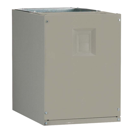
MB6BM, MB6EM, & MB6VM Series
INSTALLATION INSTRUCTIONS
MODULAR INDOOR BLOWER
Please read all information in this manual thoroughly and become familiar with the capabilities
and use of your appliance before attempting to operate or maintain this unit. These instructions
are primarily intended to assist qualifi ed individuals experienced in the proper installation of
this appliance. Some local codes require licensed installation / service personnel for this type
of equipment. Improper installation, service, adjustment, or maintenance may cause explosion,
fi re, electrical shock or other hazardous conditions which may result in personal injury or
property damage.
Unless otherwise noted in these instructions, only factory authorized kits or accessories may
be used with this product. Keep this manual where you have easy access to it in the future. If a
problem occurs, check the instructions and follow recommendations given. If these suggestions
don't eliminate your problem, call your servicing contractor.
IMPORTANT
DO NOT DESTROY. PLEASE READ CAREFULLY AND
KEEP IN A SAFE PLACE FOR FUTURE REFERENCE.
Advertisement
Table of Contents

Summary of Contents for Nordyne MB6BM Series
- Page 1 MB6BM, MB6EM, & MB6VM Series INSTALLATION INSTRUCTIONS MODULAR INDOOR BLOWER IMPORTANT Please read all information in this manual thoroughly and become familiar with the capabilities and use of your appliance before attempting to operate or maintain this unit. These instructions are primarily intended to assist qualifi...
-
Page 2: Table Of Contents
TABLE OF CONTENTS Figure 7. MB6 Series Dimensions ......16 Figure 8. MB6 Series Components ......17 Important Safety Information ........2 Blower Performance Data ........18 Requirements & Codes ..........3 Table 4. MB6BM Airfl ow Data .......18 Table 5. MB6EM Airfl ow Data .......19 General Information ...........4 Table 6. -
Page 3: Requirements & Codes
IMPORTANT SAFETY INFORMATION • Installation of equipment may require brazing operations. Installer must comply with safety codes and wear INSTALLER: Please read all instructions before servicing appropriate safety equipment (safety glasses, work this equipment. Pay attention to all safety warnings and gloves, fi... -
Page 4: General Information
GENERAL INFORMATION Locating the Indoor Blower • Survey the job site to determine the best location for This appliance has been tested for capacity and effi ciency mounting the unit. Consideration should be given to in accordance with A.H.R.I. Standards and will provide availability of electric power, service access, and noise. -
Page 5: Plenums & Air Ducts
blower must be cleaned and/or repaired if found to with standard practice as specifi ed in the ASHRAE be dirty, damaged, or malfunctioning in any way by a recommendations for duct transitions. qualifi ed HVAC technician. The indoor blower shall be •... -
Page 6: Air Filters
• Modular indoor blowers are intended to be mated with gasket tape to the top of the coil case (except the rear specifi c NORDYNE C6 cased coils. To ensure proper surface). Make sure there are no gaps on the front and condensate drainage, the unit must be installed in a side fl... -
Page 7: Downfl Ow Installation
3. Remove the lower front bracket (Figure 9, page 17) from the modular unit. Retain the screws for later use. 4. Attach the front joining bracket to the front of the modular unit. Align the screw holes in the bracket with the holes from the lower front bracket and the top panel of the coil case. -
Page 8: Horizontal Installation
4. Carefully place the cased coil on top of the modular air handler. NOTE: Make sure the units are fl ush in the front and on the sides with a “step” fi t in the back and that there are no gaps on the sides. See Figure 4. 5. -
Page 9: Electrical Connections
ELECTRICAL CONNECTIONS • Use only copper wire for the line voltage power supply to this unit. Use proper code agency listed conduit and a conduit connector for connecting the supply wires to WARNING: the unit. Aluminum supply wire may be used if a heater ELECTRICAL SHOCK, FIRE OR EXPLOSION kit is installed. -
Page 10: Control Board
on an outside wall or any other location where its Twinning operation may be adversely affected by radiant heat from MB6 indoor blowers are not supplied with a built in twinning fi replaces, sunlight, or lighting fi xtures, and convective capability. -
Page 11: Optional Humidistat
When electric heat packages with circuit breakers are Optional Humidistat fi eld-installed, the circuit breaker may be used as a (MB6VM Models Only) disconnecting means in most applications. Reference the The optional humidistat may be installed in the return air NEC and local codes for disconnect requirements. - Page 12 Figure 6. Typical Air Conditioner & Heat Pump System Connections...
-
Page 13: Startup & Adjustments
STARTUP & ADJUSTMENTS Turning the Blower Off Set thermostat’s fan mode to AUTO, the blower will shut Before You Start the Unit down immediately. Prior to start-up, complete the following inspections: Verify the unit is level and properly located with adequate Blower Confi... -
Page 14: Variable Speed Units
Variable Speed Units (MB6VM Models) IMPORTANT! If coil icing is observed, the basic cooling/ Variable Speed units have been designed to give heat-pump airfl ow selected may be too low. Verify the the installer maximum fl exibility to optimize system setting selected is within the range shown in Table # and performance, effi... -
Page 15: Unit Maintenance
UNIT MAINTENANCE Inspect and replace the air fi lter at the beginning of heating and cooling season. It is recommended that the fi lter Proper maintenance is most important to achieve the be cleaned or replaced monthly. Newly built or recently best performance from an indoor blower. -
Page 16: Figures & Tables
FIGURES & TABLES 3/4 TYP. 3/4 TYP. 12 7/8 VIEW Ø1 1/8” K.O. (TYP.) 1 1/4 "A" Ø 1 7/8 K.O. 2 7/8 1 3/4 1 1/4 3 1/4 2 5/8 1” 1 7/8 1 7/8 3 1/2 5 1/2 Ø... - Page 17 Outlet Heater Box Heating Element Assembly Transformer Control Board Blower Wheel Blower Blower Rear Housing Door Bracket Motor Control Blower Board Motor Motor Lower Front Mount Kit Bracket Front Joining Bracket Coil Assembly Figure 8. MB6 Series Components...
-
Page 18: Blower Performance Data
BLOWER PERFORMANCE DATA MB6BM Airfl ow Data Dry Coil ESP 0.10 0.20 0.30 0.40 0.50 0.60 0.70 0.80 Corrected ESP 0.07 0.19 0.30 0.42 0.53 0.65 0.76 0800 A-Cabinet Corrected ESP 0.11 0.23 0.36 0.48 0.60 0.72 High 1070 1025 Corrected ESP 0.14 0.27... - Page 19 MB6EM Airfl ow Data Dry Coil ESP 0.10 0.20 0.30 0.40 0.50 0.60 0.70 0.80 Tap 1 Corrected ESP 0.08 0.19 0.30 0.42 0.53 0.64 0.75 Tap 2 Corrected ESP 0.07 0.18 0.29 0.40 0.51 0.62 0.73 Tap 3 1200 A-Cabinet Corrected ESP 0.03...
- Page 20 A-CABINET B-CABINET C-CABINET Switch Nominal Switch Nominal Switch Nominal Number Capacity Number Capacity Number Capacity 4 1.5 2 2.5 3 4 1.5 2 2.5 3 3.5 4 3 3.5 4 1075 1135 1225 1295 1380 1040 1460 1085 1525 1140 1625 1015 1205...
-
Page 21: Electrical Diagrams
ELECTRICAL DIAGRAMS G Y/Y2 O W1 W2 Y1 L2COM2 FUSE 24VAC L2COM V.S. CONNECTOR VSPOWER XFMR COOL HEAT Figure 9. MB6BM & MB6VM Control Board G Y/Y2 O W1 W2 Y1 FUSE 24VAC L2COM L1/VSPOWER XFMR X13 COOL X13 HEAT X13 COM Figure 10. - Page 22 Y/Y2 Figure 11. Variable Speed Motor Control Board...
- Page 23 PLUG 6 = LOW GREY BLACK TRANSFORMER WHITE 1=COM 2=CAP BROWN 3=CAP 4=HIGH 5=MED 6=LOW BLACK 3 SPD. MOTOR Legend Field Wiring ¢7105381¤ Factory Wiring Low Voltage High Voltage 710538A 710538A Figure 12. Wiring Diagram for MB6BM Series Indoor Blower...
- Page 24 WIRING DIAGRAM Air Handler NOTES: blower motor X13 MOTOR speed tap connection may not be as shown. Installation Instructions. Disconnect all power before servicing. POWER SUPPLY Transformer may have a dual voltage primary tap. Match position with CUT WIRES TO REMOVE supply voltage used.
- Page 25 Figure 14. Wiring Diagram for MB6VM Series Indoor Blower...
-
Page 28: Installation / Performance Checklist
INSTALLATION / PERFORMANCE CHECK LIST ELECTRICAL SYSTEM: ATTENTION INSTALLERS: Electrical connections tight? It is your responsibility to know this product better than your customer. This includes being able to install the product according to strict Line voltage polarity correct? safety guidelines and instructing the customer on how to operate and maintain the equipment for the life of the product.
Need help?
Do you have a question about the MB6BM Series and is the answer not in the manual?
Questions and answers