Table of Contents
Advertisement
Quick Links
TrynEx International, LLC, 531 Ajax Drive, Madison Heights, MI 48071-2429 • www.snowexproducts.com
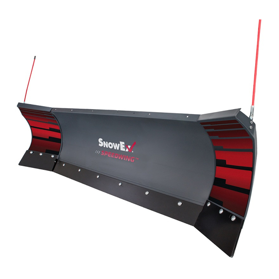
SPEEDWING™ Snowplow
8600
77740, 77840, 77840-1, 77840-3
Installation Instructions
Read this document before installing the
snowplow.
See your SnowEx
vehicle application recommendations before
installation. The Power Match selection
system has specifi c vehicle and snowplow
requirements.
A DIVISION OF DOUGLAS DYNAMICS, LLC
CAUTION
CAUTION
outlet/website for specifi c
®
May 1, 2021
Lit. No. 52308, Rev. 06
Advertisement
Table of Contents

Subscribe to Our Youtube Channel
Summary of Contents for Douglas Dynamics SnowEx Automatixx SPEEDWING 8600
- Page 1 CAUTION Read this document before installing the snowplow. CAUTION See your SnowEx outlet/website for specifi c ® vehicle application recommendations before installation. The Power Match selection system has specifi c vehicle and snowplow requirements. A DIVISION OF DOUGLAS DYNAMICS, LLC...
-
Page 2: Safety Definitions
SAFETY SAFETY DEFINITIONS WARNING/CAUTION AND INSTRUCTION LABELS WARNING Become familiar with and inform users about the Indicates a potentially hazardous situation warning/caution and instruction labels on the back of that, if not avoided, could result in death or the blade. serious personal injury. -
Page 3: Safety Precautions
SAFETY SAFETY PRECAUTIONS HYDRAULIC SAFETY Improper installation and operation could cause WARNING personal injury and/or equipment and property damage. Hydraulic fl uid under pressure can cause skin Read and understand labels and the Owner's Manual injection injury. If you are injured by hydraulic before installing, operating, or making adjustments. -
Page 4: Battery Safety
SAFETY FIRE AND EXPLOSION NOISE Airborne noise emission during use is below 70 dB(A) WARNING for the snowplow operator. Gasoline is highly fl ammable and gasoline vapor is explosive. Never smoke while VIBRATION working on vehicle. Keep all open fl ames away from gasoline tank and lines. -
Page 5: Installation Instructions
INSTALLATION INSTRUCTIONS UNPACKING AND REMOVING SHIPPING A-FRAME HOLE POSITION BRACKETS IMPORTANT! Before assembling headgear to A-frame, measure the vehicle mount height to 1. Set aside the blade guides and parts bags. The confi rm whether standard receivers or tall receivers vehicle electrical harnesses and Owner's Manual are required, and which A-frame holes to use for packet are in the bag with the headlamp box. - Page 6 INSTALLATION INSTRUCTIONS A-FRAME TO HEADGEAR 3. Fold the headgear forward and pin the lift cylinder to the A-frame using a 2-1/8" x 1/2" clevis pin and 1-1/2" x 5/32" cotter pin from the parts bag. 1. Position the A-frame between the headgear strut and inner ear, aligning the appropriate hole in the 4.
- Page 7 INSTALLATION INSTRUCTIONS A-FRAME TO BLADE ASSEMBLY 4. Remove the protective packaging from the angle rams. 1. Align the pivot bolt hole on the A-frame with the 5. Align the holes in the rod end of the angle ram pivot bolt hole on the quadrant. with the corresponding holes on the back of the quadrant.
- Page 8 INSTALLATION INSTRUCTIONS Insert the threaded end of the cable through the 9. Stand the blade and A-frame assembly upright and driver-side pivot bushing from the center out. support it in a level position using a block under the Slide the cable through the spring until the eyelet main A-frame tube.
- Page 9 INSTALLATION INSTRUCTIONS HEADLAMPS From inside the headlamp channel, insert the cable tie anchors into the holes as shown. The anchor locking tabs should be horizontal. WARNING Your vehicle must be equipped with snowplow headlamps and directional lights. Cable Tie Headlamps, hardware, and instructions are found in Anchors Grommet the headlamp box.
-
Page 10: Hydraulic Unit
OPERATIONAL TEST AND FINAL ADJUSTMENTS HYDRAULIC UNIT WARNING To prevent accidental movement of the blade, WARNING always turn the control OFF whenever the snowplow is not in use. The power indicator Keep 8' clear of the blade when it is being light will turn OFF. - Page 11 OPERATIONAL TEST AND FINAL ADJUSTMENTS BLADE DROP SPEED ADJUSTMENT FINAL INSPECTION AND ADJUSTMENT WARNING WARNING Keep 8' clear of the blade when it is being Keep 8' clear of the blade when it is being raised, lowered or angled. Do not stand raised, lowered or angled.
-
Page 12: Cable Adjustment
OPERATIONAL TEST AND FINAL ADJUSTMENTS CABLE ADJUSTMENT 3. Return the blade to the straight position and adjust the hex nut 1/4 turn clockwise. Angle the blade fully left and inspect the area between the wing 1. Angle the blade fully left and inspect the area stop and the rib again. - Page 13 OPERATIONAL TEST AND FINAL ADJUSTMENTS 5. Once the stop is making contact with the rib, lock 6. Repeat Steps 1–5 on the passenger's side of the the hex nut into position with the 3/4" jam nut. blade assembly, this time angling the blade fully to the right.
- Page 14 OPERATIONAL TEST AND FINAL ADJUSTMENTS VEHICLE LIGHTING CHECK options available, checking the functionality of the snowplow DRLs will depend on the type of module installed on the vehicle. 1. Verify the operation of all vehicle front lighting prior to connecting the snowplow harness. With the headlamp switch OFF, activate the vehicle DRLs.
- Page 15 OPERATIONAL TEST AND FINAL ADJUSTMENTS WING LOCK PINS AND LIFT LOCK PINS OWNER'S MANUAL PACKET The parts bag contains two 3/4" x 9" clevis pins for If the completed snowplow will be delivered pinning the wings in the straight position as a plowing immediately, the Owner's Manual should be reviewed option.
- Page 16 Do not exceed vehicle ratings with a snowplow. TrynEx International off ers a limited warranty for all snowplows and accessories. See separately printed page for this important information. The following are registered ( ® or unregistered (™) trademarks of Douglas Dynamics, LLC: Automatixx , POWER PLOW™, SnowEx , SPEEDWING™.


Need help?
Do you have a question about the SnowEx Automatixx SPEEDWING 8600 and is the answer not in the manual?
Questions and answers