
Related Manuals for Motomaster 299-7001-6

Summary of Contents for Motomaster 299-7001-6
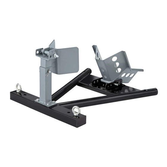
- Page 1 299-7001-6 HEAVY-DUTY MOTORCYCLE WHEEL CHOCK Please read this manual carefully before operating the product and save it for reference.
- Page 2 299-7001-6 1-888-942-6686 1-888-942-6686.
-
Page 3: Table Of Contents
TABLE OF CONTENTS Speci cations Personal Protective Equipment Speci c Safety Precautions Assembly Instructions Operating Instructions Maintenance Troubleshooting Parts List Warranty SAVE THESE INSTRUCTIONS This manual contains important safety and operating instructions. Read all instructions and follow them while using the products. -
Page 4: Speci Cations
299-7001-6 1-888-942-6686 . 009-0037-6 SPECIFICATIONS Capacity Wheel Diameter Net Weight 1500 lb (680 kg) 16 – 21" (40.6 – 53.3 cm) 17 lb 10 oz (8 kg) INTRODUCTION 199-1501-x The motorcycle wheel chock securely supports your motorcycle in an upright position with a locking cradle. -
Page 5: Personal Protective Equipment
PERSONAL PROTECTIVE EQUIPMENT • Always wear impact safety goggles that provide front and side protection for the eyes. Eye protection equipment should comply with CSA Z94.3-07 or ANSI Z87.1 standards based on the type of work performed. • Wear gloves that provide protection based on the work materials or to reduce the effects of tool vibration. -
Page 6: Speci C Safety Precautions
299-7001-6 1-888-942-6686 . 009-0037-6 SPECIFIC SAFETY PRECAUTIONS • Use the correct tool for the job. This tool was designed for a speci c function. Do not modify or alter this tool or use it for an unintended purpose. Never attempt to exceed the chock’s weight capacity (see Speci cations). -
Page 7: Assembly Instructions
ASSEMBLY INSTRUCTIONS Connect tire stop upper pole (3) and lower pole (4), aligning the holes in the desired position. Secure in place with the R clip for pole connection (6). fig A R clip for pole connection (6) Tire stop lower pole (4) Tire stop upper pole (3) Secure the tire stop lower pole (4) to the base (9) using the four bolts and spring... - Page 8 299-7001-6 1-888-942-6686 . 009-0037-6 Place the tire stop (1) on upper pole (3), aligning the holes in the desired position. Secure in place with the bolt set (2). fig C Tire stop (1) Upper pole (3) Bolt set (2) Place the wheel cradle (12) at the bottom end of the base (9), aligning the holes in the desired position.
-
Page 9: Operating Instructions
OPERATING INSTRUCTIONS Adjusting the tire stop and wheel cradle Tire stop locking position Tire stop • The tire stop has 2 locking positions and the wheel cradle Wheel cradle has 5 locking positions. To adjust the positions, extract the R clip R clip and withdraw the pin. -
Page 10: Maintenance
299-7001-6 1-888-942-6686 . 009-0037-6 Removing motorcycle from the chock • More effort will be required to remove the motorcycle from the chock. Ensure that the space into which the motorcycle will move is free from obstructions and people. • Take a rm stance and hold the motorcycle handlebar grips. -
Page 11: Troubleshooting
TROUBLESHOOTING Use the table below to troubleshoot problems before contacting service personnel or your local dealer. If the problem continues after troubleshooting, call your local dealer for assistance. Failure Possible Cause Corrective Action Screw loose Tighten the screw with correct screwdriver Wheel too big Change the wheel cradle position to... - Page 12 299-7001-6 1-888-942-6686 . 009-0037-6 No. Description Qty. No. Description Qty. Tire stop Base eyebolt M10x110 bolt set M8x15 bolt & spring washer Tire stop upper pole Base Tire stop lower pole Wheel cradle pin 11.5x123 Pole connect pin 11.5x68 R clip for wheel cradle...
-
Page 13: Warranty
WARRANTY This Motomaster product carries a one (1) year warranty against defects in workmanship and materials. At its discretion, Motomaster Canada agrees to have any defective part(s) repaired or replaced free of charge, within the stated warranty period, when returned by the original purchaser with proof of purchase. - Page 14 N° de modèle : 299-7001-6 CALE DE ROUE DE MOTOCYCLETTE ROBUSTE IMPORTANT : GUIDE Veuillez lire attentivement ce guide avant d'utiliser l'article D’UTILISATION et le conserver aux ns de consultation ultérieure.
- Page 15 N° de modèle : 299-7001-6 / Communiquez avec nous au 1 888 942-6686 S'IL Y A DES PIÈCES MANQUANTES OU ENDOMMAGÉES, OU SI VOUS AVEZ LA MOINDRE QUESTION, VEUILLEZ COMMUNIQUER AVEC LE SERVICE D'ASSISTANCE TÉLÉPHONIQUE SANS FRAIS AU 1 888 942-6686.
- Page 16 TABLE DES MATIÈRES Fiche technique Équipement de protection individuelle Consignes de sécurité spéci ques Instructions d'assemblage Consignes d'utilisation Entretien Dépannage Liste des pièces Garantie CONSERVEZ CES CONSIGNES Le présent guide contient d'importantes consignes de sécurité et de fonctionnement. Veuillez lire toutes les consignes et les respecter pendant que vous utilisez cet article.
-
Page 17: Fiche Technique
N° de modèle : 299-7001-6 / Communiquez avec nous au 1 888 942-6686 . 009-0037-6 FICHE TECHNIQUE Capacité Diamètre de la roue Poids Net 1500 lb (680 kg) 16 à 21 po (40,6 à 53,3 cm) 17 lb 10 oz (8 kg) -
Page 18: Équipement De Protection Individuelle
ÉQUIPEMENT DE PROTECTION INDIVIDUELLE • Portez toujours des lunettes antiprojections qui offrent une protection frontale et latérale pour les yeux. L'équipement de protection des yeux devrait être conforme à la norme CSA Z94.3-07 ou ANSI Z87.1 en fonction du type de travail effectué. Portez des gants qui protègent en fonction des matériaux de travail et pour réduire les effets des vibrations de l'outil. -
Page 19: Consignes De Sécurité Spéci Ques
N° de modèle : 299-7001-6 / Communiquez avec nous au 1 888 942-6686 . 009-0037-6 CONSIGNES DE SÉCURITÉ SPÉCIFIQUES • Utilisez le bon outil pour la tâche à effectuer. Cet outil a été conçu pour une utilisation spéci que. Évitez de modi er ou d'altérer cet outil ou de l'utiliser à une n autre que celle pour laquelle il a été... -
Page 20: Instructions D'assemblage
INSTRUCTIONS D’ASSEMBLAGE Assemblez le poteau supérieur (3) au poteau inférieur (4) de la butée de roue en alignant les trous à la position souhaitée. Fixez l'assemblage au moyen de la goupille bêta (6). fig A Goupille bêta (6) pour la xation des poteaux Poteau inférieur (4) de la butée de roue... - Page 21 N° de modèle : 299-7001-6 / Communiquez avec nous au 1 888 942-6686 . 009-0037-6 Placez la butée de roue (1) sur le poteau supérieur (3) en alignant les trous en position souhaitée. Fixez-la au moyen de l'ensemble du boulon (2) de la butée de roue.
-
Page 22: Consignes D'utilisation
CONSIGNES D’UTILISATION Réglage de la butée de roue et du berceau de roue • La butée de roue comprend 2 positions Position de verrouillage de la butée de roue de blocage et le berceau de roue Butée de roue comprend 5 positions de blocage. Pour Berceau de roue régler les positions, retirez les goupilles bêta et les tiges. -
Page 23: Entretien
N° de modèle : 299-7001-6 / Communiquez avec nous au 1 888 942-6686 . 009-0037-6 Retrait de la motocyclette de la cale de roue • Un effort supplémentaire est nécessaire pour retirer la motocyclette de la cale de roue. Assurez-vous que l'espace vers lequel la motocyclette sera déplacée est libre de personnes et d’objets. -
Page 24: Dépannage
DÉPANNAGE Consultez le tableau ci-dessous pour résoudre les problèmes avant de prendre contact avec le personnel de service ou votre revendeur local. Si le problème persiste après le dépannage, communiquez avec votre revendeur local pour obtenir de l'aide. Échec Cause possible Mesure corrective Screw loose Serrez les vis à... - Page 25 N° de modèle : 299-7001-6 / Communiquez avec nous au 1 888 942-6686 . 009-0037-6 N° Description Qté N° Description Qté 1 Butée de roue 7 Piton pour base 2 Ensemble du boulon M10 x 110 8 Ensemble de boulons et de rondelles 3 Poteau supérieur de la butée de roue...
-
Page 26: Garantie
GARANTIE Cet article Motomaster comprend une garantie d’un (1) an contre les défauts de fabrication et de matériau(x). Motomaster Canada consent, à sa discrétion, à réparer ou à remplacer toute pièce défectueuse sans frais au cours de la période de garantie convenue lorsque l’article, accompagné...
Need help?
Do you have a question about the 299-7001-6 and is the answer not in the manual?
Questions and answers