Table of Contents
Advertisement
Quick Links
CG-1001
November 23, 2020
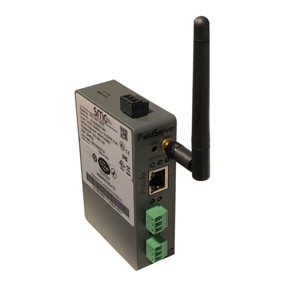
MB485ETH-CG
Communication Gateway
Installation and Operation
1
DESCRIPTION
The MB485ETH-CG communication gateway is an
accessory designed to allow any Modbus-capable
Fireye control to communicate to a building
management system or PLC using the BACnet/IP,
BACnet MS/TP, EtherNet/IP or Modbus TCP/IP
protocols. Multiple devices can be connected to a single
communication gateway. Configuration is done using
any web browser connected to the same network as the
communication gateway, or wirelessly via the built-in
access point.
Additionally, the communication gateway provides
remote monitoring capabilities through the cloud using
SMC Cloud services.
© 2020 Carrier
1
Advertisement
Table of Contents

Summary of Contents for Fireye MB485ETH-CG
-
Page 1: Description
November 23, 2020 MB485ETH-CG Communication Gateway Installation and Operation DESCRIPTION The MB485ETH-CG communication gateway is an accessory designed to allow any Modbus-capable Fireye control to communicate to a building management system or PLC using the BACnet/IP, BACnet MS/TP, EtherNet/IP or Modbus TCP/IP protocols. - Page 2 Technical Support Thank you for purchasing the MB485ETH-CG. Please call Fireye for technical support of this product. Please note that the manufacturer (MSA Safety dba Sierra Monitor) does not provide direct support for this Fireye-branded product. Support Contact Information: Fireye, Inc.
- Page 3 1. Record the information about the unit. (Section 4.1) 2. Check that the MB485ETH-CG and customer device COM settings match. (Section 4.3) 3. Connect the MB485ETH-CG 3 pin RS-485 R1 port to the RS-485 network connected to each of the devices. (Section 5.1) 4.
-
Page 4: Table Of Contents
4.3.2 Set Node-ID for Any Device Attached to the MB485ETH-CG ..........12 4.3.3 Set IP Address for Any Ethernet Device Connected to the MB485ETH-CG ......12 Attaching the Antenna ........................12 Interfacing MB485ETH-CG to Devices ..................... 13 Device Connections to MB485ETH-CG ..................13 Wiring Field Port to RS-485 Serial Network ................. - Page 5 Appendix A.8 Internet Browser Software Support ................... 51 Appendix B Additional Information ......................52 Appendix B.1 Updating Firmware ......................52 Appendix B.2 BACnet: Setting Network_Number for More Than One MB485ETH-CG on the Subnet .. 52 Appendix B.3 Mounting ........................... 53 Appendix B.4 Physical Dimension Drawing .................... 54 Appendix B.5 Change Web Server Security Settings After Initial Setup ..........
- Page 6 Figure 4: Points per Device ......................... 11 Figure 5: COM Settings ..........................12 Figure 6: RS-485 Connections from Devices to the MB485ETH-CG ............13 Figure 7: Connection from MB485ETH-CG to RS-485 Field Network ............13 Figure 8: Bias Resistor DIP Switches ......................14 Figure 9: Termination Resistor DIP Switch ....................
- Page 7 Figure 61: Edit User Window ........................60 Figure 62: Setup Users ..........................61 Figure 63: User Delete Warning ......................... 61 Figure 64: MB485ETH-CG Password Update via FS-GUI ................. 62 Figure 65: SMC Cloud Connection Problems Message ................63 Figure 66: Specifications ..........................65...
-
Page 8: Certification
Testing Laboratory ® 1 The BTL Mark on the MB485ETH-CG is a symbol that indicates that a product has passed a series of rigorous tests conducted by an independent laboratory which verifies that the product correctly implements the BACnet features claimed in the listing. -
Page 9: Introduction
The MB485ETH-CG can connect with the SMC Cloud. The SMC Cloud allows technicians, the OEM's support team and MSA Safety's support team to remotely connect to the MB485ETH-CG. The SMC Cloud provides the following capabilities for any registered devices in the field: •... -
Page 10: Methods Of Configuration
Methods of Configuration Devices Communication Protocol YB110_FSG Modbus RTU PPC4000_NXF4000 Modbus RTU ZB110_FSG Modbus RTU PPC6000_NX6100 Modbus RTU E110 Modbus RTU MicroM Modbus RTU BurnerPRO_Gen_3 Modbus RTU NXCESO2 Modbus RTU FX_Series_Servos Modbus RTU ACS550 Modbus RTU Insight_Insight_II_Scanner Modbus RTU NXTSD507HD_NXTSD512HD Modbus TCP/IP Figure 1: Method of Configuration for the Devices ©... -
Page 11: Mb485Eth-Cg Setup
MB485ETH-CG SETUP Record Identification Data Each MB485ETH-CG has a unique part number located on the side or the back of the unit. This number should be recorded, as it may be required for technical support. The numbers are as follows:... -
Page 12: Configuring Device Communications
Ensure the device is set to Modbus TCP/IP to communicate with the MB485ETH-CG. • • The device needs to be on the same IP subnet as the MB485ETH-CG and the configuration PC. Record the following device information to start the setup: •... -
Page 13: Interfacing Mb485Eth-Cg To Devices
INTERFACING MB485ETH-CG TO DEVICES Device Connections to MB485ETH-CG The MB485ETH-CG has a 3-pin Phoenix connector for connecting RS-485 devices on the R1 port. See specific device bulletins for details on how to properly connect Modbus to each. NOTE: Use standard grounding principles for RS-485 GND. -
Page 14: Bias Resistors
To enable Bias Resistors, move both the BIAS- and BIAS+ dip switches to the right as shown in Figure The MB485ETH-CG bias resistors are used to keep the RS-485 bus to a known state, when there is no transmission on the line (bus is idling), to help prevent false bits of data from being detected. The bias resistors typically pull one line high and the other low - far away from the decision point of the logic. -
Page 15: Termination Resistor
Figure 9: Termination Resistor DIP Switch If the MB485ETH-CG is the last device on the serial trunk, then the End-Of-Line Termination Switch needs to be enabled. To enable the Termination Resistor, move the TERM dip switch to the right as shown Figure Termination resistor is also used to reduce noise. -
Page 16: Power-Up Mb485Eth-Cg
Appendix C.1. complies with the specifications provided in The MB485ETH-CG accepts 9-30VDC or 24VAC on pins L+ and N-.The NXF4000 or PPC4000 • can supply 24VDC voltage, all other devices will require an external 24VDC power supply. Frame GND should be connected. -
Page 17: Connect To The Mb485Eth-Cg
CONNECT TO THE MB485ETH-CG Connect the PC to the MB485ETH-CG There are two ways to connect the PC to the MB485ETH-CG, either by Ethernet cable (Section 6.1.1) or Wi-Fi Access Point (Section 6.1.2). 6.1.1 Connecting to the MB485ETH-CG via Ethernet Connect a Cat-5 Ethernet cable (straight through or cross-over) between the local PC and MB485ETH-CG. -
Page 18: Connecting To The Mb485Eth-Cg Over Wi-Fi Access Point
6.1.2 Connecting to the MB485ETH-CG Over Wi-Fi Access Point When the MB485ETH-CG is first powered up, the Wi-Fi Access Point will be enabled allowing direct connection to the MB485ETH-CG with Wi-Fi. To connect to the MB485ETH-CG Wi-Fi Access Point: Click the icon (found in the bottom-right corner of the computer screen) to open the available •... -
Page 19: Setup Web Server Security
SETUP WEB SERVER SECURITY Navigate to the IP Address of the MB485ETH-CG on the local PC by opening a web browser and entering the IP Address of the MB485ETH-CG; the default Ethernet address is 192.168.1.24, the default Wi-Fi Access Point address is 192.168.50.1. -
Page 20: Figure 15: Warning Expanded Text
When the login screen appears, put in the Username (default is “admin”) and the Password (found • on the label of the MB485ETH-CG). NOTE: There is also a QR code in the top right corner of the MB485ETH-CG label that shows the default unique password when scanned. Figure 16: MB485ETH-CG Login NOTE: A user has 5 attempts to login then there will be a 10-minute lockout. -
Page 21: Select The Security Mode
Select the Security Mode On the first login to the MB485ETH-CG, the following screen will appear that allows the user to select which mode the MB485ETH-CG should use. Figure 17: Security Mode Selection Screen NOTE: Cookies are used for authentication. -
Page 22: Https With Own Trusted Tls Certificate
7.2.1 HTTPS with Own Trusted TLS Certificate This is the recommended selection and the most secure. • Once this option is selected, the Certificate, Private Key and Private Key Passphrase fields will appear under the mode selection. Figure 18: Security Mode Selection Screen – Certificate & Private Key Copy and paste the Certificate and Private Key text into their respective fields. -
Page 23: Configure Network Settings
CONFIGURE NETWORK SETTINGS Navigate to the Network Settings • From the Web App landing page, click the Settings tab on the left side of the screen. Figure 19: Web App Landing Page • Click the Network tab that appears to open the Network Settings page. Figure 20: Settings Tabs •... -
Page 24: Change The Mb485Eth-Cg Ip Address
Configure the IP settings of the MB485ETH-CG using the following methods: • When using the Ethernet port to connect to the local network (Section 8.2.2). When connecting the MB485ETH-CG to a local wireless network, configure the Wi-Fi Client • Settings in the MB485ETH-CG (Section 8.2.3). -
Page 25: Wired Network Settings
• NOTE: If the webpage was open in a browser, the browser will need to be pointed to the new IP Address of the MB485ETH-CG before the webpage will be accessible again. Figure 23: Ethernet Port Network Settings © 2020 Carrier... -
Page 26: Wi-Fi Client Settings
8.2.3 Wi-Fi Client Settings To change the Wi-Fi client settings, follow these instructions: • Set the Wi-Fi Status to ENABLED for the MB485ETH-CG to communicate with other devices via Wi-Fi. • Enter the Wi-Fi SSID and Wi-Fi Password for the local wireless network. -
Page 27: Wi-Fi Access Point Settings
8.2.4 Wi-Fi Access Point Settings To change the Wi-Fi AP settings, follow these instructions: • The Access Point Status Field must be ENABLED to allow connecting to the MB485ETH-CG via Wi-Fi. • Modify the Settings manually as needed, via these fields: Access Point SSID, Access Point Password, SSID Broadcast, and Channel. -
Page 28: Smc Cloud User Setup, Registration And Login
The SMC Cloud is MSA Safety’s device cloud solution for IIoT. Integration with the SMC Cloud enables a secure remote connection to field devices through a MB485ETH-CG and hosts local applications for device configuration, management, as well as maintenance. For more information... -
Page 29: Figure 27: Smc Cloud Opt Out Warning Window
MB485ETH-CG configuration) To ignore SMC Cloud setup until the next time the MB485ETH-CG Web App is opened, click a tab other than SMC Cloud™ and then click the Exit Registration button with the “Opt out” checkbox unchecked (skip to Section... -
Page 30: User Setup
User Setup Before the gateway can be connected to SMC Cloud a user account must be created. Request an invitation to SMC Cloud from the manufacturer’s support team and follow the instructions below to set up login details: The “Welcome to SMC Cloud” email will appear as shown below. •... -
Page 31: Figure 29: Setting User Details
Click the “Complete Registration” button and fill in user details accordingly. • Figure 29: Setting User Details Fill in the name, phone number, password fields and click the checkbox to agree to the privacy • policy and terms of service. NOTE: If access to data logs using RESTful API is needed, do not include “#”... -
Page 32: Registration Process
Registration Process Once SMC Cloud user credentials have been generated, the MB485ETH-CG can be registered onto the SMC Cloud server. When first logging onto the MB485ETH-CG, the Web App will open on the SMC Cloud™ page. • NOTE: If a warning message appears instead, go to Appendix B.7... -
Page 33: Figure 31: Smc Cloud Registration - Installer Details
To register, fill in the user details, site details, gateway details and SMC Cloud account credentials. • Enter user details and click Next Figure 31: SMC Cloud Registration – Installer Details Enter the site details by entering the physical address fields or the latitude and longitude then click Next Figure 32: SMC Cloud Registration –... -
Page 34: Figure 33: Smc Cloud Registration - Gateway Details
Enter Name and Description (required) then click Next Figure 33: SMC Cloud Registration – Gateway Details Enter user credentials and click Register Device Figure 34: SMC Cloud Registration – SMC Cloud Account © 2020 Carrier... -
Page 35: Figure 35: Device Registered For Smc Cloud
• Close button and the following screen will appear listing the device details and additional information auto-populated by the MB485ETH-CG. Figure 35: Device Registered for SMC Cloud NOTE: Update these details at any time by going to the SMC Cloud™ tab and clicking the Update Device Details button. -
Page 36: Login To Smc Cloud
Login to SMC Cloud After the MB485ETH-CG is registered, go to www.smccloud.net and type in the appropriate login information as per registration credentials. Figure 36: SMC Cloud Login Page NOTE: If the login password is lost, see the SMC Cloud Start-up Guide for recovery instructions. -
Page 37: Figure 38: Smc Cloud Landing Page
NOTE: For additional SMC Cloud instructions see the SMC Cloud Start-up Guide. Figure 38: SMC Cloud Landing Page © 2020 Carrier... -
Page 38: Configure The Mb485Eth-Cg
10 CONFIGURE THE MB485ETH-CG 10.1 Navigate to the MB485ETH-CG Web Configurator 39), click the Settings tab and then click Configuration. • From the Web App Device List page (Figure Figure 39: Web App Landing Page NOTE: For information on the System Status button, go to Appendix B.8. -
Page 39: Select Field Protocol And Set Configuration Parameters
• options for each parameter under the Parameter Description in parentheses. NOTE: If multiple devices are connected to the MB485ETH-CG, set the BACnet Virtual Server Nodes field to “Yes”; otherwise leave the field on the default “No” setting. © 2020 Carrier... -
Page 40: Setting Mb485Eth-Cg Active Profiles
10.3 Setting MB485ETH-CG Active Profiles In the Web Configurator, the Active Profiles are shown below the configuration parameters. The • Active Profiles section lists the currently active device profiles, including previous Web Configurator additions. This list is empty for new installations, or after clearing all configurations. -
Page 41: Verify Device Communications
To add an active profile to support a device, click the Add button under the Active Profiles heading. • This will present a drop-down menu underneath the Current profile column. • Once the Profile for the device has been selected from the drop-down list, enter the value of the device’s Node-ID which was assigned in Section 4.3.2. -
Page 42: Bacnet: Setting Node_Offset To Assign Specific Device Instances
10.5 BACnet: Setting Node_Offset to Assign Specific Device Instances Follow the steps outlined in Section 10.1 to access the MB485ETH-CG Web Configurator. • • The Node_Offset field shows the current value (default = 50,000). The values allowed for a BACnet Device Instance can range from 1 to 4,194,303 •... -
Page 43: How To Start The Installation Over: Clearing Profiles
10.6 How to Start the Installation Over: Clearing Profiles Follow the steps outlined in Section 10.1 to access the MB485ETH-CG Web Configurator. • • At the bottom-left of the page, click the “Clear Profiles and Restart” button. • Once restart is complete, all past profiles discovered and/or added via Web configurator are deleted. -
Page 44: Appendix A Troubleshooting
Appendix A Troubleshooting Appendix A.1 Lost or Incorrect IP Address • Ensure that MB485ETH-CG Toolbox is loaded onto the local PC. Otherwise, download the MB485ETH-CG-Toolbox.zip via the Sierra Monitor website’s Software Downloads. • Extract the executable file and complete the installation. -
Page 45: Appendix A.2 Viewing Diagnostic Information
Appendix A.2 Viewing Diagnostic Information Type the IP Address of the MB485ETH-CG into the web browser or use the MB485ETH-CG • Toolbox to connect to the MB485ETH-CG. Click on Diagnostics Button, then click on view, and then on connections. •... -
Page 46: Appendix A.3 Checking Wiring And Settings
Verify the device was listed under the Web Configurator Active Profiles (Section 10.3) No COMS on Modbus TCP/IP side. To fix, check the following: • A.4) Visual observations of LEDs on the MB485ETH-CG (Appendix Check device address Verify wiring Verify all the Modbus TCP/IP device(s) were listed in the Web Configurator (Section 10.3) •... -
Page 47: Appendix A.4 Led Diagnostics For Communications Between Mb485Eth-Cg And Devices
Appendix A.4 LED Diagnostics for Communications Between MB485ETH-CG and Devices See the diagram below for MB485ETH-CG FPA-W44 LED Locations. FPA-W44 Diagnostic LEDs Description The SS LED will flash once a second to indicate that the bridge is in operation. The SYS ERR LED will go on solid indicating there is a system error. If this occurs, immediately report the related “system error”... -
Page 48: Appendix A.5 Taking A Mb485Eth-Cg Diagnostic Capture
Once the Diagnostic Capture is complete, email it to technical support. The Diagnostic Capture will accelerate diagnosis of the problem. If the MB485ETH-CG bios is updated/released on November 2017 or later then the Diagnostic Capture is performed via the gateway’s on-board system. -
Page 49: Appendix A.5.1 Taking A Capture With Older Firmware
Appendix A.5.1 Taking a Capture with Older Firmware If the MB485ETH-CG firmware is from before November 2017, the Diagnostic Capture can be done by downloading the MB485ETH-CG Toolbox software but network connections (such as Ethernet and Wi-Fi) cannot be captured (if a network diagnostic is needed take a Wire Shark capture). - Page 50 Select “Full Diagnostic" from the drop down menu NOTE: If desired, the default capture period can be changed. Click on the Start Diagnostic button Wait for the capture period to finish and the Diagnostic Test Complete window will appear • Step 2: Send Log Once the diagnostic test is complete, a .zip file is saved on the PC Choose “Open”...
-
Page 51: Appendix A.6 Wi-Fi Signal Strength
Microsoft Edge Rev. 41 and higher • • Safari Rev. 3 and higher NOTE: Internet Explorer is no longer supported as recommended by Microsoft. NOTE: Computer and network firewalls must be opened for Port 80 to allow MB485ETH-CG GUI to function. © 2020 Carrier... -
Page 52: Appendix B Additional Information
To load a new version of the firmware, follow these instructions: 1. Extract and save the new file onto the local PC. 2. Open a web browser and type the IP Address of the MB485ETH-CG in the address bar. Default IP Address is 192.168.1.24... -
Page 53: Appendix B.3 Mounting
Appendix B.3 Mounting The MB485ETH-CG can be mounted using the DIN rail mounting bracket on the back of the unit. Din Rail Bracket Figure 53: DIN Rail © 2020 Carrier... -
Page 54: Appendix B.4 Physical Dimension Drawing
Appendix B.4 Physical Dimension Drawing Power Port Wi-Fi Antenna Socket R2 Serial Port R1 Serial Port Figure 54: MB485ETH-CG FPA-W44 Dimensions © 2020 Carrier... -
Page 55: Appendix B.5 Change Web Server Security Settings After Initial Setup
Appendix B.5 Change Web Server Security Settings After Initial Setup NOTE: Any changes will require a MB485ETH-CG reboot to take effect. • From the FS-GUI page, click Setup in the Navigation panel. Figure 55: FS-GUI Landing Screen © 2020 Carrier... -
Page 56: Appendix B.5.1 Change Security Mode
Appendix B.5.1 Change Security Mode Click Security in the Navigation panel. • Figure 56: FS-GUI Security Setup Click the Mode desired. • If HTTPS with own trusted TLS certificate is selected, follow instructions in Section 7.2.1 Click the Save button. •... -
Page 57: Appendix B.5.2 Edit The Certificate Loaded Onto The Mb485Eth-Cg
Appendix B.5.2 Edit the Certificate Loaded onto the MB485ETH-CG NOTE: A loaded certificate will only be available if the security mode was previously setup as HTTPS with own trusted TLS certificate. Click Security in the Navigation panel. • Figure 57: FS-GUI Security Setup – Certificate Loaded Click the Edit Certificate button to open the certificate and key fields. -
Page 58: Appendix B.6 Change User Management Settings
Figure 58: FS-GUI User Management User Types: Admin – Can modify and view any settings on the MB485ETH-CG. Operator – Can modify and view any data in the MB485ETH-CG array(s). Viewer – Can only view settings/readings on the MB485ETH-CG. © 2020 Carrier... -
Page 59: Appendix B.6.1.1 Create Users
Appendix B.6.1.1 Create Users Click the Create User button. • Figure 59: Create User Window • Enter the new User fields: Name, Security Group and Password. User details are hashed and salted NOTE: The password must meet the minimum complexity requirements. An algorithm automatically checks the password entered and notes the level of strength on the top right of the Password text field. -
Page 60: Appendix B.6.2 Edit Users
Appendix B.6.2 Edit Users Click the pencil icon next to the desired user to open the User Edit window. • Figure 60: Setup Users Once the User Edit window opens, change the User Security Group and Password as needed. • Figure 61: Edit User Window •... -
Page 61: Appendix B.6.2.1 Delete Users
Appendix B.6.2.1 Delete Users Click the trash can icon next to the desired user to delete the entry. • Figure 62: Setup Users When the warning message appears, click Confirm. • Figure 63: User Delete Warning © 2020 Carrier... -
Page 62: Appendix B.6.3 Change Mb485Eth-Cg Password
Figure 64: MB485ETH-CG Password Update via FS-GUI • Change the general login password for the MB485ETH-CG as needed. NOTE: The password must meet the minimum complexity requirements. An algorithm automatically checks the password entered and notes the level of strength on the top right of the Password text field. -
Page 63: Appendix B.7 Smc Cloud Connection Warning Message
NOTE: If changes to the network settings are done, remember to click the Save button. Then power cycle the MB485ETH-CG by clicking on the Confirm button in the window and click on the bolded “Restart” text in the yellow pop-up box that appears in the upper right corner of the screen. -
Page 64: Appendix B.8 System Status Button
Appendix B.8 System Status Button The System Status Button can be found on any page of the web apps. This shows the level of alert/functionality for the customer device. This is an agragate of the Web App page’s resource usage upon the local PC or mobile device, SMC Cloud connectivity and device alert level. -
Page 65: Appendix C Reference
Figure 66: Specifications Appendix C.1.1 Compliance with UL Regulations For UL compliance, the following instructions must be met when operating MB485ETH-CG. • The units shall be powered by listed LPS or Class 2 power supply suited to the expected operating temperature range. -
Page 66: Appendix D Device Mapping
Appendix D Device Mapping Check the specific gateway start-up guide for the supported protocols for the gateway in use. The protocols listed below may not apply to the gateway. NOTE: For the headings below “BACnet” references both BACnet/IP and BACnet MS/TP. NOTE: All Modbus TCP/IP registers are the same as the Modbus RTU registers for the serial device. -
Page 67: Appendix D.1 Yb110_Fsg Modbus Rtu Mappings To Field Protocols
Appendix D.1 YB110_FSG Modbus RTU Mappings to Field Protocols BACnet BACnet LonWorks SNVT Point Name Object Object EIP Tag Name LonWorks Name Class Attribute Address Offset Type Type Safety_Relay Bit_XXX[000] nvoSafetyRel_XXX SNVT_switch Main_Valve_In Bit_XXX[001] nvoMainVlvIn_XXX SNVT_switch Delayed_Valve_In Bit_XXX[002] nvoDelVlvIn_XXX SNVT_switch Pilot_Valve_In Bit_XXX[003] nvoPltVlvIn_XXX... - Page 68 BACnet BACnet LonWorks SNVT Point Name Object Object EIP Tag Name LonWorks Name Class Attribute Address Offset Type Type Lockout7_BnrHrs U32_XXX[015] nvoLkot7BrHr_XXX SNVT_time_hour Lockout7_BnrCycs U32_XXX[016] nvoLkot7BrCy_XXX SNVT_count_f Lockout8_Msg U16_XXX[057] nvoLkot8Msg_XXX SNVT_count_f Lockout8_Module U16_XXX[058] nvoLkot8Mod_XXX SNVT_count_f Lockout8_BnrHrs U32_XXX[017] nvoLkot8BrHr_XXX SNVT_time_hour Lockout8_BnrCycs U32_XXX[018] nvoLkot8BrCy_XXX SNVT_count_f...
-
Page 69: Appendix D.2 Ppc4000_Nxf4000 Modbus Rtu Mappings To Field Protocols
Appendix D.2 PPC4000_NXF4000 Modbus RTU Mappings to Field Protocols BACnet BACnet LonWorks SNVT Point Name Object Object EIP Tag Name LonWorks Name Class Attribute Address Offset Type Type Operational State Flt_XXX[000] nvoOpState_XXX SNVT_count_f Flame Signal Value Flt_XXX[001] nvoFlmSigVal_XXX SNVT_count_f System On Hours Flt_XXX[002] nvoSysHrs_XXX SNVT_time_hour... - Page 70 BACnet BACnet LonWorks SNVT Point Name Object Object EIP Tag Name LonWorks Name Class Attribute Address Offset Type Type Fault 2 - Error Code Flt_XXX[062] nvoFt2ErCod_XXX SNVT_count_f Fault 2 - Time Of Fault Occ Flt_XXX[063] nvoFt2TimFlt_XXX SNVT_count_f Fault 2 Date Of Fault Occ Day/Hour Flt_XXX[064] nvoFt2DtDyHr_XXX SNVT_count_f...
- Page 71 BACnet BACnet LonWorks SNVT Point Name Object Object EIP Tag Name LonWorks Name Class Attribute Address Offset Type Type Sensor 1 Margin Alarm Value Flt_XXX[126] nvoSn1MgAlVl_XXX SNVT_count_f Sensor 1 Limit Alarm Value Flt_XXX[127] nvoSn1LmAlVl_XXX SNVT_count_f Sensor 2 Set Point Value Flt_XXX[128] nvoSn2SPVl_XXX SNVT_count_f...
-
Page 72: Appendix D.3 Zb110_Fsg Modbus Rtu Mappings To Field Protocols
Appendix D.3 ZB110_FSG Modbus RTU Mappings to Field Protocols BACnet BACnet LonWorks SNVT Point Name Object Object EIP Tag Name LonWorks Name Class Attribute Address Offset Type Type STATUS U16_XXX[000] nvoStatus_XXX SNVT_count_f MSGN U16_XXX[001] nvoMsgn_XXX SNVT_count_f GSTAT U16_XXX[002] nvoGstat_XXX SNVT_count_f TIMER U16_XXX[003] nvoTimer_XXX... - Page 73 BACnet BACnet LonWorks SNVT Point Name Object Object EIP Tag Name LonWorks Name Class Attribute Address Offset Type Type 05th_LCKOUT_BHRS U32_XXX[011] nvo5Lkot_Bhr_XXX SNVT_time_hour 05th_LCKOUT_BCYC U32_XXX[012] nvo5Lkot_Bcy_XXX SNVT_count_f 06th_LCKOUT_MSG U16_XXX[045] nvo6Lkot_Msg_XXX SNVT_count_f 06th_LCKOUT_MOD U16_XXX[046] nvo6Lkot_Mod_XXX SNVT_count_f 06th_LCKOUT_BHRS U32_XXX[013] nvo6Lkot_Bhr_XXX SNVT_time_hour 06th_LCKOUT_BCYC U32_XXX[014] nvo6Lkot_Bcy_XXX SNVT_count_f...
- Page 74 BACnet BACnet LonWorks SNVT Point Name Object Object EIP Tag Name LonWorks Name Class Attribute Address Offset Type Type AUX 1 Sensor Marginal ALM U16_XXX[100] nvoAx1SnMgAl_XXX SNVT_count_f AUX 1 Sensor Limit ALM U16_XXX[101] nvoAx1SnLmAl_XXX SNVT_count_f AUX 2 Sensor Use U16_XXX[102] nvoAux2SnUse_XXX SNVT_count_f AUX 2 Sensor Type...
-
Page 75: Appendix D.4 Ppc6000_Nx6100 Modbus Rtu Mappings To Field Protocols
Appendix D.4 PPC6000_NX6100 Modbus RTU Mappings to Field Protocols BACnet BACnet LonWorks SNVT Point Name Object Object EIP Tag Name LonWorks Name Class Attribute Address Offset Type Type Setpoint Select Bit_XXX[000] nvi/nvoSPSelect_XXX SNVT_switch Release to Ignite Bit_XXX[001] nvi/nvoRel2Ignit_XXX SNVT_switch Low Fire Hold Bit_XXX[002] nvi/nvoLoFireHld_XXX SNVT_switch... - Page 76 BACnet BACnet LonWorks SNVT Point Name Object Object EIP Tag Name LonWorks Name Class Attribute Address Offset Type Type Engineers Key 022 AI_XXX[072] nvoEngKey022_XXX SNVT_count_f Engineers Key 023 AI_XXX[073] nvoEngKey023_XXX SNVT_count_f Engineers Key 024 AI_XXX[074] nvoEngKey024_XXX SNVT_count_f Engineers Key 025 AI_XXX[075] nvoEngKey025_XXX SNVT_count_f...
- Page 77 BACnet BACnet LonWorks SNVT Point Name Object Object EIP Tag Name LonWorks Name Class Attribute Address Offset Type Type Engineers Key 086 AI_XXX[136] nvoEngKey086_XXX SNVT_count_f Engineers Key 087 AI_XXX[137] nvoEngKey087_XXX SNVT_count_f Engineers Key 088 AI_XXX[138] nvoEngKey088_XXX SNVT_count_f Engineers Key 089 AI_XXX[139] nvoEngKey089_XXX SNVT_count_f...
- Page 78 BACnet BACnet LonWorks SNVT Point Name Object Object EIP Tag Name LonWorks Name Class Attribute Address Offset Type Type Engineers Key 150 AI_XXX[200] nvoEngKey150_XXX SNVT_count_f Engineers Key 151 AI_XXX[201] nvoEngKey151_XXX SNVT_count_f Engineers Key 152 AI_XXX[202] nvoEngKey152_XXX SNVT_count_f Engineers Key 153 AI_XXX[203] nvoEngKey153_XXX SNVT_count_f...
- Page 79 BACnet BACnet LonWorks SNVT Point Name Object Object EIP Tag Name LonWorks Name Class Attribute Address Offset Type Type Fault Log Item 01 Minute 1015 Log_XXX[014] nvoF01Minute_XXX SNVT_count_f Fault Log Item 01 Subset 1016 Log_XXX[015] nvoF01Subset_XXX SNVT_count_f Fault Log Item 02 Fault Num 1017 Log_XXX[016] nvoF02FltNum_XXX SNVT_count_f...
- Page 80 BACnet BACnet LonWorks SNVT Point Name Object Object EIP Tag Name LonWorks Name Class Attribute Address Offset Type Type Fault Log Item 09 Minute 1079 Log_XXX[078] nvoF09Minute_XXX SNVT_count_f Fault Log Item 09 Subset 1080 Log_XXX[079] nvoF09Subset_XXX SNVT_count_f Fault Log Item 10 Fault Num 1081 Log_XXX[080] nvoF10FltNum_XXX SNVT_count_f...
- Page 81 BACnet BACnet LonWorks SNVT Point Name Object Object EIP Tag Name LonWorks Name Class Attribute Address Offset Type Type Fault Log Item 17 Minute 1143 Log_XXX[142] nvoF17Minute_XXX SNVT_count_f Fault Log Item 17 Subset 1144 Log_XXX[143] nvoF17Subset_XXX SNVT_count_f Fault Log Item 18 Fault Num 1145 Log_XXX[144] nvoF18FltNum_XXX SNVT_count_f...
-
Page 82: Appendix D.5 E110 Modbus Rtu Mappings To Field Protocols
Appendix D.5 E110 Modbus RTU Mappings to Field Protocols BACnet BACnet LonWorks SNVT Point Name Object Object EIP Tag Name LonWorks Name Class Attribute Address Offset Type Type STATUS U16_XXX[000] nvoStatus_XXX SNVT_count_f MSGN U16_XXX[001] nvoMsgn_XXX SNVT_count_f GSTAT U16_XXX[002] nvoGstat_XXX SNVT_count_f TIMER U16_XXX[003] nvoTimer_XXX... - Page 83 BACnet BACnet LonWorks SNVT Point Name Object Object EIP Tag Name LonWorks Name Class Attribute Address Offset Type Type E300 Aux 1 Bit_XXX[033] nvoE3Aux1_XXX SNVT_switch E300 Aux 2 Bit_XXX[034] nvoE3Aux2_XXX SNVT_switch E300 High Water Bit_XXX[035] nvoE3HiWtr_XXX SNVT_switch E300 High Temp Bit_XXX[036] nvoE3HiTmp_XXX SNVT_switch...
-
Page 84: Appendix D.6 Microm Modbus Rtu Mappings To Field Protocols
Appendix D.6 MicroM Modbus RTU Mappings to Field Protocols BACnet BACnet LonWorks SNVT Point Name Object Object EIP Tag Name LonWorks Name Class Attribute Address Offset Type Type STATUS U16_XXX[000] nvoStatus_XXX SNVT_count_f MSGN U16_XXX[001] nvoMsgn_XXX SNVT_count_f GSTAT U16_XXX[002] nvoGstat_XXX SNVT_count_f TIMER U16_XXX[003] nvoTimer_XXX... -
Page 85: Appendix D.7 Burnerpro_Gen_3 Modbus Rtu Mappings To Field Protocols
Appendix D.7 BurnerPRO_Gen_3 Modbus RTU Mappings to Field Protocols BACnet BACnet LonWorks SNVT Point Name Object Object EIP Tag Name LonWorks Name Class Attribute Address Offset Type Type Burner On/Off U16_XXX[000] nvi/nvoBrnOnOff_XXX SNVT_switch Lockout Reset U16_XXX[001] nvi/nvoLckotRes_XXX SNVT_switch Product Id U16_XXX[002] nvoProdId_XXX SNVT_count_f... - Page 86 BACnet BACnet LonWorks SNVT Point Name Object Object EIP Tag Name LonWorks Name Class Attribute Address Offset Type Type Lockout History 6 Reason Code U16_XXX[062] nvoLH6RsnCd_XXX SNVT_count_f Lockout History 6 Burner State U16_XXX[063] nvoLH6BrnSt_XXX SNVT_count_f Lockout History 6 Burner Minutes U16_XXX[064] nvoLH6BrnMn_XXX SNVT_count_f...
-
Page 87: Appendix D.8 Nxces02 Modbus Rtu Mappings To Field Protocols
Appendix D.8 NXCES02 Modbus RTU Mappings to Field Protocols BACnet BACnet LonWorks SNVT Point Name Object Object EIP Tag Name LonWorks Name Class Attribute Address Offset Type Type Probe Status U16_XXX[000] nvi/nvoPrbStat_XXX SNVT_count_inc_f Probe Status Sensor Byt_XXX[000] nvoPrbStaSen_XXX SNVT_count_inc_f Probe Status CPU Byt_XXX[001] nvoPrbStaCPU_XXX SNVT_count_inc_f... -
Page 88: Appendix D.9 Fx_Series_Servos Modbus Rtu Mappings To Field Protocols
Appendix D.9 FX_Series_Servos Modbus RTU Mappings to Field Protocols BACnet BACnet LonWorks SNVT Point Name Object Object EIP Tag Name LonWorks Name Class Attribute Address Offset Type Type Commanded Position Srv_XXX[000] nvoCmdPos_XXX SNVT_count_inc_f Current Servo Position Srv_XXX[001] nvoCurSrvPos_XXX SNVT_count_inc_f Tweak Mode Error Percent and Rot Dir Srv_XXX[002] nvoTwkErrPer_XXX SNVT_count_inc_f... - Page 89 BACnet BACnet LonWorks SNVT Point Name Object Object EIP Tag Name LonWorks Name Class Attribute Address Offset Type Type Servo Cmd Position at Speed 51 Wrt_XXX[050] nviSrvCdPs51_XXX SNVT_count_inc_f Servo Cmd Position at Speed 52 Wrt_XXX[051] nviSrvCdPs52_XXX SNVT_count_inc_f Servo Cmd Position at Speed 53 Wrt_XXX[052] nviSrvCdPs53_XXX SNVT_count_inc_f...
-
Page 90: Appendix D.10 Acs550 Modbus Rtu Mappings To Field Protocols
Appendix D.10 ACS550 Modbus RTU Mappings to Field Protocols BACnet BACnet LonWorks SNVT Point Name Object Object EIP Tag Name LonWorks Name Class Attribute Address Offset Type Type OFF1 DO_XXX[000] nvi/nvoOff1_XXX SNVT_swtich OFF2 DO_XXX[001] nvi/nvoOff2_XXX SNVT_swtich OFF3 DO_XXX[002] nvi/nvoOff3_XXX SNVT_swtich START DO_XXX[003] nvi/nvoStart_XXX... -
Page 91: Appendix D.11 Insight_Insight_Ii_Scanner Modbus Rtu Mappings To Field Protocols
Appendix D.11 Insight_Insight_II_Scanner Modbus RTU Mappings to Field Protocols BACnet BACnet LonWorks SNVT Point Name Object Object EIP Tag Name LonWorks Name Class Attribute Address Offset Type Type UV DATA POINT 1 S16_XXX[000] nvoUV_Pnt_1_XXX SNVT_count_inc_f UV DATA POINT 2 S16_XXX[001] nvoUV_Pnt_2_XXX SNVT_count_inc_f UV DATA POINT 3... - Page 92 BACnet BACnet LonWorks SNVT Point Name Object Object EIP Tag Name LonWorks Name Class Attribute Address Offset Type Type SCANNER OPTIONS 2 S16_XXX[062] nvoScnOpt2_XXX SNVT_count_inc_f SCANNER TEMPERATURE S16_XXX[063] nvoScnTem_XXX SNVT_count_inc_f SCANNER FILE IN USE S16_XXX[064] nvoScnFlInUs_XXX SNVT_count_inc_f SCANNER LIFETIME ERROR COUNT U32_XXX[000] nvoScnLfErCt_XXX SNVT_count_inc_f...
- Page 93 BACnet BACnet LonWorks SNVT Point Name Object Object EIP Tag Name LonWorks Name Class Attribute Address Offset Type Type FILE D: IR BANDPASS S16_XXX[128] nvoD_IRBndPs_XXX SNVT_count_inc_f FILE D: UV BANDPASS S16_XXX[129] nvoD_UVBndPs_XXX SNVT_count_inc_f FILE D: IR FRONT END GAIN S16_XXX[130] nvoD_IRFntGn_XXX SNVT_count_inc_f FILE D: UV FRONT END GAIN...
- Page 94 BACnet BACnet LonWorks SNVT Point Name Object Object EIP Tag Name LonWorks Name Class Attribute Address Offset Type Type LEARNT AVG OFF FFT FOR IR POINT 6 S16_XXX[192] nvoLnOffIR6_XXX SNVT_count_inc_f LEARNT AVG OFF FFT FOR IR POINT 7 S16_XXX[193] nvoLnOffIR7_XXX SNVT_count_inc_f LEARNT AVG OFF FFT FOR IR POINT 8 S16_XXX[194]...
-
Page 95: Appendix D.12 Nxtsd507Hd_Nxtsd512Hd Modbus Tcp/Ip Mappings To Field Protocols
Appendix D.12 NXTSD507HD_NXTSD512HD Modbus TCP/IP Mappings to Field Protocols BACnet BACnet LonWorks SNVT Point Name Object Object EIP Tag Name LonWorks Name Class Attribute Address Offset Type Type Current Operational State Srv_XXX[000] nvoCurOpStat_XXX SNVT_count_inc_f Flame Signal Value Srv_XXX[001] nvoFlmSigVal_XXX SNVT_count_inc_f Operational Hour Counter Srv_XXX[002] nvoOpHrCnt_XXX... - Page 96 BACnet BACnet LonWorks SNVT Point Name Object Object EIP Tag Name LonWorks Name Class Attribute Address Offset Type Type Servo 2 Commanded Position Srv_XXX[062] nvoSv2CmdPos_XXX SNVT_count_inc_f Servo 2 Current Position Srv_XXX[063] nvoSv2CurPos_XXX SNVT_count_inc_f Servo 3 Command Srv_XXX[064] nvoSv3Cmd_XXX SNVT_count_inc_f Servo 3 Data Length Srv_XXX[065] nvoSv3DatLen_XXX SNVT_count_inc_f...
- Page 97 BACnet BACnet LonWorks SNVT Point Name Object Object EIP Tag Name LonWorks Name Class Attribute Address Offset Type Type Current Active Error Number Srv_XXX[126] nvoCurActErr_XXX SNVT_count_inc_f Total Number Of Errors Detected Srv_XXX[127] nvoNumErrDet_XXX SNVT_count_inc_f Lockout History 1 Operation State Srv_XXX[128] nvoLH1_OpSt_XXX SNVT_count_inc_f Lockout History 1 Profile Position...
- Page 98 BACnet BACnet LonWorks SNVT Point Name Object Object EIP Tag Name LonWorks Name Class Attribute Address Offset Type Type Lockout History 7 Error Code Srv_XXX[190] nvoLH7_ErrCd_XXX SNVT_count_inc_f Lockout History 7 Sec Srv_XXX[191] nvoLH7_Sec_XXX SNVT_count_inc_f Lockout History 7 Min Srv_XXX[192] nvoLH7_Min_XXX SNVT_count_inc_f Lockout History 7 Hour Srv_XXX[193]...
- Page 99 Force User Output 1 Srv_XXX[303] nvi/nvoFrcUsrOt1_XXX SNVT_switch Force User Output 2 Srv_XXX[304] nvi/nvoFrcUsrOt2_XXX SNVT_switch Force User Output 3 Srv_XXX[305] nvi/nvoFrcUsrOt3_XXX SNVT_switch Fireye, Inc. CG-1001 3 Manchester Road November 23, 2020 Derry, NH 03038 Supercedes August 28, 2020 www.fireye.com © 2020 Carrier...