Advertisement
Table of Contents
Tekno RC Adjustable Wing Mount for T-Maxx
Thank you for your purchase and support. You'll nd this wing
mount to be easy to install and extremely durable. Please read and
follow the instructions carefully to ensure proper installation and
long product life. Thanks again!
STEP 01 - Remove rear shock tower. You should be able to easily
reach and unscrew the 4 screws securing the rear shock tower. Next,
remove the shocks from the tower (don't remove from a-arms). You
should also remove the body mount posts for easier assembly.
(Shock mount and wing shown for illustrative purposes only and are
not included)
Look at Fig. 01 (below) and decide which Height / Angle mounting
hole combination you are going to run. We recommend starting
with the B-2 combination and adjusting from there.
STEP 02 - ***USE THREAD LOCKING COMPOUND ON THE
M3x16mm BUTTON HEAD SCREWS AND ALUMINUM BRACES***
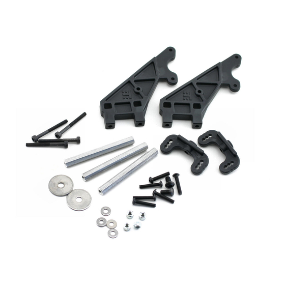
Starting with the two top aluminum braces and the nylon washers,
loosely assemble the wing mount as shown in Fig. 2. When every-
thing is in place, tighten up the 6 M3 x 16mm screws (remember the
thread locking compound). Set the wing mount assembly aside for
now.
STEP 03 – Next we will secure the wing mount assembly to the
shock tower as shown in Fig. 3.
Start by inserting the 4 long screws (M3 x 30mm) into the X-brace,
followed by the 8mm spacers.
Carefully position the shock tower and shock tower brace onto the
X-brace assembly. Hold the loose assembly in one hand and place
the wing mount assembly over the 4 protruding screws.
Fig. 3a shows a side view of the assembly. Note that the top two
8mm spacers should be sitting on top of the shock tower.
Insert the lower screws (M3 x 20mm) into the shock tower brace
through the shock tower to properly align the wing mount with the
shock tower.
Place the supplied M3 locknuts into the cutouts on the wing mount
brackets and secure the wing mount assembly to the shock tower
one screw at a time. You may need to wedge a small at screw driver
into the locknut cutouts to prevent the locknuts from spinning
while tightening them down.
STEP 04 – Mount the wing of your choice (Fig. 04 on reverse
side). Use the included drill template (below right) to help with
drilling holes in your wing. Mugen wings already have holes
drilled the proper distance apart. You may need to widen the
holes a bit for a perfect t. Other wings may also t directly if
they share the same dimensions as the Mugen wing.
If you lose or misplace the template, the wing mount posts are
40mm apart (center to center) and are 8mm in diameter.
Secure the wing using the supplied M4x16mm button head
screws, large stainless steel washers, and M4 locknuts.
STEP 05 - Reattach the shocks to the shock tower. Next, secure
DRILL TEMPLATE
Advertisement
Table of Contents

Summary of Contents for Tekno RC TKR1009
- Page 1 Tekno RC Adjustable Wing Mount for T-Maxx 40mm apart (center to center) and are 8mm in diameter. Secure the wing using the supplied M4x16mm button head screws, large stainless steel washers, and M4 locknuts. Thank you for your purchase and support. You’ll nd this wing mount to be easy to install and extremely durable.
- Page 2 We tried to avoid this, but any sort of mount will more than likely require body modi cations. Thank you for choosing Tekno RC! Check www.teknorc.com for great deals on all of your hobby needs including kits, hop-ups, spare parts, radios, servos, tools, accessories, and more.


Need help?
Do you have a question about the TKR1009 and is the answer not in the manual?
Questions and answers