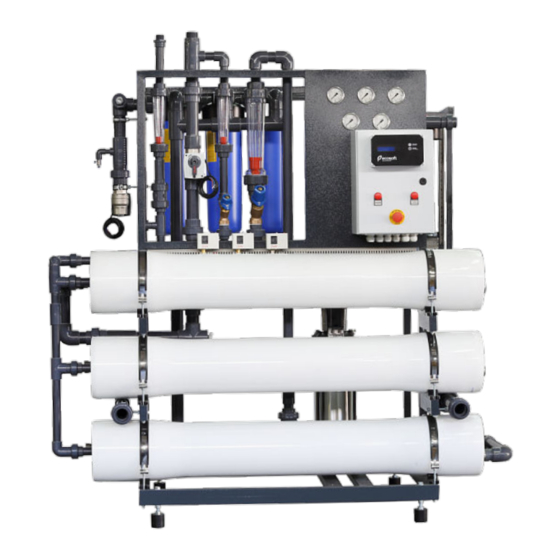
Ecosoft MO-1 Instruction Manual
Ecosoft mo midi systems
Hide thumbs
Also See for MO-1:
- Instruction manual (102 pages) ,
- Instruction manual (102 pages) ,
- Instruction manual (102 pages)
Table of Contents
Advertisement
Quick Links
Advertisement
Table of Contents

Related Manuals for Ecosoft MO-1


Summary of Contents for Ecosoft MO-1
- Page 1 INSTRUCTION MANUAL Ecosoft MO MIDI systems MO-1 MO-2 MO-3 MO-4 MO-6 MO-9...
-
Page 3: Table Of Contents
Acronyms and abbreviations RO system 1. Overview 2. Technical data 3. Installation and startup 4. Installation requirements 5. Operating requirements 6. Shipping and storage requirements 7. Troubleshooting CONTROLLER 1. Overview 2. Technical data 3. Operating modes 4. Program Annex A. Bypass valve P&IDs Annex B. -
Page 4: Acronyms And Abbreviations
Ecosoft industrial reverse osmosis systems are used for demi- neralizing water in industrial, municipal, commercial applications. Ecosoft RO system can be used to demineralize low to medium salinity feed water. All parts of the system that are in contact with water have the necessary certifications for use in food/drinking water applications. -
Page 5: Technical Data
Improperly commissioned RO system may fail in the matter of minutes, including irreparable membrane failure, hardware failure, and also involves electrical and pressure hazard. Drain flow rate and recycle flow rates should only be configured by authorized staff. Permeate stream comes out via permeate outlet and runs to permeate tank. -
Page 7: Installation And Startup
LIMITATIONS 150 mg/L CaCO Hardness 8,5 °dH Iron 0,1 mg/L Manganese 0,05 mg/L Silicate 20 mg/L Total dissolved solids 3000 mg/L Chemical oxygen demand 4,0 mg/L O Residual chlorine 0,1 mg/L Hydrogen sulfide none the limitations may be exceeded if using antiscalant, oxygen scavenger, or other RO chemical pretreatment 0,2…0,4 MPa Inlet pressure... - Page 8 Remove PVC piping with the pressure vessel ports. To remove PVC pipes, take apart pipe unions at the pressure vessel ports. If necessary, also loosen next closest downstream union to remove the entire piping fragment leading to the vessel. Remove the lid at the feed end of pressure vessel. First, remove spiral retaining ring by pulling bent tab towards the center of circle.
- Page 9 drain tube or hose with drain outlet of the RO system and run it to drain pipe. Ensure air gap at the end of drain line to prevent backsiphonage. Connect tube or hose to permeate outlet and extend it to permeate tank. Cut or bore an aperture at the top of tank wall, install pipe gland and pull the permeate tube through the gland (note: run permeate line to drain when carrying out initial membrane rinse).
- Page 10 Main circuit Controller Protection breaker circuit breaker relay Top DIN rail in the power cabinet 3-phase Pump Bottom DIN rail in the power cabinet power contactor connection...
- Page 11 3.7 Start up the system as follows : 3.7.1 Ensure recycle and drain flow regulating valves are fully open before starting. Run the permeate tube to drain for the duration of the first run of the RO system. 3.7.2 Switch on controller circuit breaker to start the RO system. After the controller starts up and the unit starts to operate, tighten drain regulating valve until drain rotameter reading meets specification (see table of Specifications).
-
Page 12: Installation Requirements
Take care not to exceed 1,4 MPa in membrane module at any time. If membrane pressure rises above the upper limit in specification, open recycle flow regulating valve to bring it down. Drain flow rate must not go below the calculated target value at any time. -
Page 13: Operating Requirements
Electrical connections must comply with local electrical code. Make sure to follow applicable grounding and insulation rules. Supply, drain, and delivery pipework must comply with local plumbing code and have sufficient flow capacity. Drain line of the unit must be separated from floor drain with an air gap. ... - Page 14 5.5 Change polypropylene cartridge when it has clogged. Pressure drop of 0,1 MPa or greater on the sediment filter indicates that filter cartridge needs to be replaced as soon as possible. 5.6 Perform CIP or another suitable chemical cleaning protocol when any of the following conditions are encountered: –...
- Page 15 – remove spent cartridge from the bowl, place a clean one inside and screw the bowl back on. Do not torque over 2 kgf×m when tightening bowl. 5.10 To replace membrane element proceed as follows: – remove the power from the unit; –...
-
Page 16: Shipping And Storage Requirements
Shipping and storage requirements The unit must be stored indoors. Ambient air quality must meet workplace standards. Carry out preservative treatment of membrane elements when preparing for an extended downtime. The RO machine in its original packaging can be shipped by all types of air, sea or ground transport. -
Page 17: Troubleshooting
Power supply fault Refer to protection relay manual or contact Ecosoft product support The controller Protection relay is Ensure clean 380-400 V, 50 Hz does not start tripped... - Page 18 The system is Set up proper connection to connected to water water supply pipe. Avoid long supply using flexible runs of small size pipe hose or small size pipe Clogged pre-filter Check the filter cartridge and cartridge replace if necessary Contact your dealer’s product Other support...
-
Page 19: Controller
performing hydraulic flushing of membranes (‘forward flush’) with preset frequency and duration; implementing manual control over the unit. In order to deliver the above functionality, Ecosoft process controller supports the following connectivity: – 5 dry contact switches (NC/NO);... -
Page 20: Technical Data
Technical data... - Page 21 Electrical cabinet components Reference Product code Product Ecosoft ОС5000 RO controller OC5000EN SM1P1400 Motor protect circuit breaker C4P1 C4 1 pole mini circuit breaker PMV50A575 Voltage control relay TDTR015 15 W 230/24 VAC voltage transformer 8LM2TB6344 Push button switch R1…R4...
-
Page 22: Operating Modes
Operating modes When operating, the controller will be in any one of the following modes: Service, Stop, Forward Flush 1, Forward Flush 2, Standby, Fault. Immediately after starting, the controller will display firmware version and then proceed to Service if tank permeate level is low and backpressure switch is not activated. - Page 23 (OC5000 only). Pushing START once will initiate Forward Flush 1, pushing START twice in 0.5 seconds or less will initiate Forward Flush 2, pushing STOP will bring on Stop mode. If high feed pressure, low feed pressure, or high permeate conductivity condition occurs, the controller will go into Fault mode.
- Page 24 Forward Flush 2 occurs after each Forward Flush 1 if configuration step 1.3 is set to non-zero value. It can be manually brought on by pushing START during Forward Flush 1 or double pushing START during Service. Status of outputs in FF2 High pressure and on (if configuration step 1.4 is set to ‘on’)
- Page 25 the controller back to Standby. When float switch or permeate backpressure switch deactivate, the controller will go back to Service. FAULT In Fault mode, the unit is stalled to protect the equipment from dangerous operating conditions. Fault mode is brought on by activating low feed pressure switch (to prevent ‘dry running’), high feed pressure switch (to protect against overpressure), or reading an excessively high permeate conductivity value (which could mean...
-
Page 26: Program
Program Configuration settings are stored in non-volatile memory. Access to each submenu is protected with passcode. To enter configuration menu, hold STOP for 8 seconds. In the menu, editing and storing values is helped by flashing cursor. START button moves cursor ... - Page 27 2. CALIBRATION Settings and calibration passcode prompt 2.1 First point value, μS/cm 2.2 Second point value, μS/cm 3. MAINTENANCE Maintenance passcode prompt 3.1 Schedule maintenance stop, on/off 3.2 Scheduled stop period, h (if 3.1 is set to ‘on’) 500 hour 3.3 New maintenance passcode 1.
- Page 28 1.7 Read low feed pressure during Forward Flush This setting specifies if low feed pressure switch status will be read by the controller during forward flush. If set to ‘off’, low feed pressure situation will not bring about Fault mode. 1.8 Low feed pressure switch This setting specifies whether low feed pressure switch is normally closed (NC) or normally open (NO) type.
- Page 29 reset to ‘off’ if 1.16 is set to ‘on’. 1.16 0…50 μS/cm conductivity range Specify if the controller will read electrical conductivity of permeate in the range of 0…50 μS/cm (on/off). This setting will reset to ‘off’ if 1.15 is set to ‘on’. 1.17 Permeate conductivity Fault threshold Specify maximum acceptable permeate conductivity.
- Page 30 into sample of known standard conductivity, wait until the reading on display stabilizes and input actual conductivity. Then go to the next step. 2.2 Second point value Use water sample with greater conductivity than that of the first point standard. Follow the same procedure rinsing and wiping residual moisture on conductivity meter electrodes.
-
Page 31: Annex A. Bypass Valve P&Ids
Bypass valve enabled system P&IDs Drain water Legend 1. entry valve 7. sediment prefilter 2. forward flush valve 8. membrane module Purified 3. bypass valve 9. permeate tank 4. dosing pump 10. drain flow control water 5. High Pressure pump 11. -
Page 32: Annex B. Operation Record
Operation record Ecosoft RO . Operation record. Pressure Flow... - Page 33 Serial number Factory Acceptance Test Protocol ____________ reverse osmosis system Ecosoft Type of test Parameter value Pass Signature □ 1. Hydraulic connections tightness □ 1.1 Water pressure at main □ 1.2 Test duration □ 1.3 No leaks detected □ 2. Valves and instruments performance □...
Need help?
Do you have a question about the MO-1 and is the answer not in the manual?
Questions and answers