Table of Contents
Advertisement
Available languages
Available languages
Quick Links
Advertisement
Chapters
Table of Contents

Summary of Contents for NetMan plus
- Page 1 0MNUSAXNPE...
- Page 2 - ITALIANO - - 2 -...
- Page 3 Questo manuale contiene le istruzioni dettagliate per l’uso e l’installazione del prodotto. Per informazioni sull’utilizzo e per ottenere il massimo delle prestazioni dalla Vostra apparecchiatura, il presente manuale dovrà essere conservato con cura vicino al NetMan plus e CONSULTATO PRIMA DI OPERARE SULLO STESSO.
-
Page 4: Table Of Contents
) __________________________________________ 16 ENSORI AMBIENTALI OPZIONALI Sensori disponibili _______________________________________________________ 16 INSTALLAZIONE E CONFIGURAZIONE _______________________________ 17 _________________________________________________ 17 ETTAGGIO DEI JUMPER _________________________________________ 19 NSTALLAZIONE PLUS _________________________________________ 19 NSTALLAZIONE PLUS ______________________________________________________ 19 ONFIGURAZIONE Configurazione via linea seriale RS-232 ______________________________________ 19 - 4 -... - Page 5 - ITALIANO - Configurazione via telnet __________________________________________________ 20 Salvataggio della configurazione e riavvio con i parametri impostati ______________ 20 Menù principale di configurazione __________________________________________ 20 Menù IP config ___________________________________________________________ 23 Menù Time setting ________________________________________________________ 24 Menù UPS config _________________________________________________________ 26 Menù...
-
Page 6: Presentazione
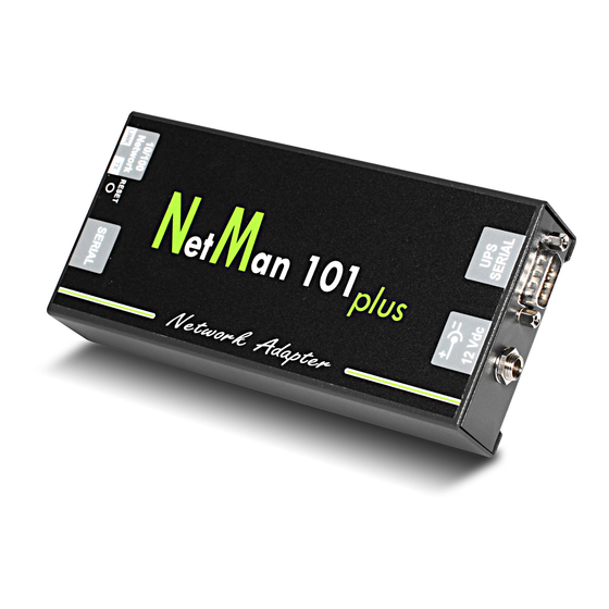
NetMan 101 plus è un accessorio esterno all’UPS da collegare ad esso tramite cavo seriale; NetMan 102 plus è una scheda di espansione da inserire nello slot dell’UPS (per i modelli che lo supportano) come indicato nella figura sottostante. Le funzionalità dei due prodotti sono le medesime e quanto descritto in questo manuale vale per entrambi (ove non diversamente specificato). -
Page 7: Apertura Dell
Dopo l’apertura dell’imballo, per prima cosa procedere alla verifica del contenuto. L’imballo dovrà contenere: NetMan 101 plus NetMan 102 plus OPPURE Alimentatore esterno 12Vdc 0,3A Cavo seriale null-modem DB9-DB9 CD-Rom (Manuale utente e file MIB) solo per NetMan 101 plus - 7 -... -
Page 8: Porta Di Rete
Monitorare l’UPS tramite linea seriale RS-232 (vedi paragrafo “Seriale RS-232”) ERVIZI DI RETE Il NetMan plus implementa una serie di servizi che si basano sui principali protocolli di rete. Questi servizi possono essere attivati o disattivati a seconda delle esigenze (vedi paragrafo “Configurazione”). -
Page 9: Http
(Internet Explorer, Safari, Firefox, Netscape Navigator, Konqueror, Opera) sono supportati. Una volta inserito l’hostname o l’idirizzo IP del NetMan plus sul vostro web browser, si visualizzerà una schermata simile alla seguente, sulla quale sono presenti i principali dati operativi dell’UPS. -
Page 10: Snmp
MIB (Management Information Base). Per ogni agent esiste un file MIB che definisce quali variabili possono essere richieste e i rispettivi diritti di accesso. Il file MIB del NetMan plus si trova all’interno del CD fornito in dotazione. L’agent può inoltre inviare messaggi (TRAP) senza una precedente richiesta da parte del manager, per informare quest’ultimo di eventi di particolare... -
Page 11: Ftp
- ITALIANO - FTP (File Transfer Protocol) è un protocollo di rete utilizzato per lo scambio di file. Il NetMan plus utilizza questo protocollo per due scopi: 1. download dei file dell’archivio storico di misure ed eventi dell’UPS (Datalog e Eventlog) 2. -
Page 12: Email
- ITALIANO - Email Il NetMan plus è in grado di inviare e-mail di notifica al verificarsi di una o più condizioni di allarme. Le e-mail possono essere inviate fino a tre destinatari ed il loro invio può essere associato a sette diversi tipi di allarme. -
Page 13: Ervizi Della Porta Di Comunicazione
Modem Tx/Rx Il NetMan plus permette di monitorare lo stato dell’UPS tramite un modem collegato alla porta di comunicazione “SERIAL”. Attivando il servizio “Modem Tx” è possibile abilitare il modem per la trasmissione; l’UPS è così in grado di effettuare delle chiamate ad una stazione di teleassistenza per notificare eventuali situazioni di allarme. -
Page 14: Seriale Rs-232
RCHIVIO STORICO DI MISURE ED EVENTI DELL Il NetMan plus effettua la registrazione su archivio storico di misure (Datalog) ed eventi (Eventlog) dell’UPS. I dati vengono salvati su file in formato testo e possono essere letti o tramite un foglio elettronico (che permette l’ordinamento cronologico dei dati) o tramite un qualunque editor di testi. -
Page 15: Datalog
- ITALIANO - Datalog Datalog è un servizio che effettua la registrazione dei principali dati dell’UPS sul file ‘data.log’. Il file può essere scaricato via FTP o può essere inviato tramite e-mail utilizzando il servizio “Email report”. I dati monitorati sono: •... -
Page 16: Sensori Ambientali
- ITALIANO - ENSORI AMBIENTALI OPZIONALI È possibile collegare al NetMan plus dei sensori ambientali per monitorare temperatura, umidità ed ingressi/uscite digitali. Le informazioni ricavate da questi sensori possono essere visualizzate tramite il software di monitoraggio e controllo dell’UPS oppure tramite web browser (il servizio HTTP deve essere attivo). -
Page 17: Installazione E Configurazione
(JP14) • Abilitare il modem (JP10) o i sensori ambientali (JP6, JP10) Per configurare correttamente i jumper, fare riferimento alle tabelle ed immagini seguenti. NetMan 101 plus NetMan 102 plus CHIUSO NON MONTATO NON MONTATO... - Page 18 JP11 Configurazione di default NetMan 102 plus (solo per NetMan 101 plus): per agire sui jumper è necessario scollegare il connettore di alimentazione, il cavo di rete e i cavi seriali, togliere le quattro viti poste nella parte inferiore del dispositivo e sfilare il coperchio.
-
Page 19: Installazione Net Man
ONFIGURAZIONE Il NetMan plus può essere configurato via linea seriale o via telnet. il NetMan plus necessita di circa 30 secondi per essere operativo dal momento in cui viene alimentato; prima di questo tempo il dispositivo potrebbe non rispondere ai... -
Page 20: Configurazione Via Telnet
Configurazione via telnet Per configurare il NetMan plus via telnet è necessario: • eseguire su un PC collegato in rete al NetMan plus un programma telnet con impostato l’indirizzo IP del dispositivo da configurare • alla richiesta di login digitare “root”... - Page 21 - ITALIANO - Da questo menù principale è possibile accedere a vari sottomenù la cui funzione è illustrata nella tabella seguente. Menu Funzione IP config Per configurare i parametri di rete Time setting Per configurare l’orologio interno UPS config Per configurare il tipo di UPS collegato Services 1 Per attivare e/o configurare i servizi del dispositivo Services 2...
- Page 22 • Line interactive: UPS in modalità “Line Interactive” • AC fail: UPS in funzionamento da batteria • Stand-by: UPS in stand-by • Communication lost: mancanza di comunicazione tra l’UPS e il NetMan plus Di seguito una rappresentazione grafica dei menu e sottomenu: - 22 -...
-
Page 23: Menù Ip Config
Tramite questo menù è possibile impostare i principali parametri di rete come descritto nella tabella seguente. Campo Parametri da inserire Hostname Digitare l’host name del NetMan plus IP address/DHCP Digitare l’indirizzo IP nel caso di IP statico; digitare “DHCP” per IP dinamico Netmask Digitare la netmask da usare assieme all’indirizzo IP statico Gateway Digitare il nome o l’indirizzo del gateway di rete... -
Page 24: Menù Time Setting
- ITALIANO - Dopo aver premuto “ESC” e “Y” per confermare l’uscita dal menù viene visualizzata una schermata che riassume i settaggi (vedi immagine seguente). Premendo il tasto “Invio” si ritorna al menù principale. È comunque necessario salvare la configurazione per renderla effettiva al riavvio del dispositivo (vedi “Menù... - Page 25 - ITALIANO - Premendo il tasto “Invio” in corrispondenza del comando ”Set time”, si visualizza una schermata simile alla seguente. Current date is Wed Jun 15 08:09:40 GMT 2005 Insert new date and clock time in this form: MMDDYYYYHHMMSS 06152005081000 Current date is Wed Jun 15 08:10:00 GMT 2005 Digitare la data e l’ora nel formato indicato e quindi premere il tasto invio e poi “ESC”...
-
Page 26: Menù Ups Config
- ITALIANO - Menù UPS config /------------------------/ UPS conf /------------------------/ PRTK Code..:GPSER11201XX Name...:ups3 Address..:1 Serial number..:324321 Tramite questo menù devono essere impostati i parametri dell’UPS, come descritto nella tabella seguente, affinché quest’ultimo possa comunicare correttamente con il dispositivo. Campo Parametri da inserire PRTK Code Digitare il codice PRTK indicato sul retro dell’UPS Name... -
Page 27: Menù Services 1
- ITALIANO - Menù Services 1 /------------------------/ Services 1 /------------------------/ SNMP config..:<-- SNMP community.: Modem config...: Modem logic..: Email config...: Email logic..: Miscellaneous..: Activation 1...: Tramite questo menù è possibile accedere alle schermate di configurazione di parte dei servizi come descritto nella tabella seguente. Menù... -
Page 28: Menù Snmp Config
- ITALIANO - Menù SNMP config /------------------------/ SNMP config /------------------------/ Trap receiver 1:powernetguard Trap receiver 2:192.168.5.96 Trap receiver 3: Trap receiver 4: Trap receiver 5: Trap receiver 6: Trap receiver 7: Tramite questo menù è possibile configurare gli indirizzi IP ai quali vengono inviate le trap. Le trap sono messaggi SNMP che vengono inviati ad un manager SNMP per la notifica di allarmi. -
Page 29: Menù Modem Config
- ITALIANO - Menù Modem config /------------------------/ Modem config /------------------------/ Phone number 1.:111 Phone number 2.:112 Phone number 3.:113 Modem init..:ATE0X0V0S0=1 Modem dial..:ATDT repeat..:3 Delay..:30 Tramite questo menù è possibile configurare il modem come descritto nella tabella seguente. Campo Parametri da inserire Phone number 1 Phone number 2 Digitare i numeri di telefono da chiamare... -
Page 30: Menù Modem Logic
INVIO per modificare la configurazione selezionata (“X”, “0”, “AND”, “OR”) • X: al verificarsi dell’evento il NetMan plus è abilitato a chiamare il corrispondente numero di telefono (vedi “Menù Modem config” per impostare i numeri di telefono da chiamare); •... -
Page 31: Menù Email Config
- ITALIANO - Eventi Significato Communic lost Comunicazione tra l’UPS e il dispositivo interrotta Presenza di una anomalia interna all’UPS (questa condizione emula il SENTR level 2 livello di allarme modem per UPS di tipo SENTR) Presenza di una anomalia nell’UPS, escluse quelle previste al punto SENTR level 3 precedente (questa condizione emula il livello di allarme modem per UPS di tipo SENTR) -
Page 32: Menù Email Logic
(vedi “Menù Email config” per impostare gli indirizzi); • 0: al verificarsi dell’evento il NetMan plus non invia una e-mail di notifica ai corrispondenti indirizzi; Nella tabella seguente viene descritto il significato degli eventi. Questi possono variare in base all’UPS collegato. -
Page 33: Menù Miscellaneous
- ITALIANO - Menù Miscellaneous /------------------------/ Miscellaneous /------------------------/ frequency..:5 Port..:33000 sysContact..:Administrator sysName..:My Server sysLocation..:new building Tramite questo menù è possibile configurare ulteriori parametri del dispositivo come descritto nella tabella seguente. Campo Parametri da inserire Digitare il ritardo, misurato in secondi, tra una registrazione dati e la Log frequency successiva (vedi paragrafo “Datalog”) UDP Port... -
Page 34: Menù Activation 1
Email...:[ON/off] Enable UDP..:[ON/off] Enable Report..:[ON/off] Tramite questo menù è possibile attivare o disattivare alcuni dei i servizi implementati nel NetMan plus: utilizzare il tasto INVIO per modificare la configurazione selezionata (“ON” o “OFF”) • ON (caratteri verdi): servizio attivo •... -
Page 35: Menù Wake-On-Lan Address
- ITALIANO - Menù Wake-On-LAN address /------------------------/ Wake-on-LAN address /------------------------/ MAC Address 1..:00-12-3F-2B-F6-6F MAC Address 2..:aa-bb-cc-dd-ee-ff MAC Address 3..:00-00-00-00-00-00 MAC Address 4..: MAC Address 5..: MAC Address 6..: MAC Address 7..: MAC Address 8..: Tramite questo menù è possibile inserire fino a 8 MAC address per eseguire il Wake-on-LAN. Assicurarsi che il proprio PC supporti tale funzione e che quest’ultima sia correttamente configurata Menù... -
Page 36: Menù Activation 2
N:[ON/off]<-- Enable Sensors.:[ON/off] Enable WOL :[on/OFF] Tramite questo menù è possibile attivare o disattivare alcuni dei servizi implementati nel NetMan plus: utilizzare il tasto INVIO per modificare la configurazione selezionata (“ON” o “OFF”). • ON (caratteri verdi): servizio attivo •... - Page 37 - ITALIANO - Esempio: collegamento di un sensore Temperature , di un sensore Humidity & Temperature e di un sensore Digital I/O & Temperature esattamente in questo ordine. Sensors Devices Press [C] to change sensors, [E] to exit Collegare il primo sensore ( Temperature ), e premere il tasto “C”.
-
Page 38: Menù I/O Sensors
Batteria scarica Communic lost Comunicazione tra l’UPS e il NetMan plus interrotta L’evento “Input sensor ” permette di associare ad una uscita digitale l’ingresso del sensore Digital I/O & Temperature installato con numero identificativo più basso (il primo rilevato in fase di installazione). -
Page 39: Menù Security
- ITALIANO - Menù Security Il menù Security si presenta con una schermata simile alla seguente. /------------------------/ Security /------------------------/ Config Password:<-- UDP Password...: Firewall..: Da questo menù è possibile configurare la password di setup, la password UDP e il firewall come descritto nella tabella seguente. - Page 40 Tramite questo menù è possibile configurare gli indirizzi IP o gli hostname dei dispositivi abilitati alla comunicazione con il NetMan plus. È possibile utilizzare il carattere “*” per uno o più campi dell’indirizzo IP ad indicare che in quel campo sono accettati tutti i valori compresi tra 0 e 255.
-
Page 41: Menù Save And Load
- ITALIANO - Menù Save and load /------------------------/ Save and load /------------------------/ Apply changes..:<-- Revert changes.: Load from file.: Save to file...: Netboot..: Reset default..: Tramite questo menù è possibile salvare la configurazione per renderla effettiva o caricare altre configurazioni come descritto nella tabella seguente. Funzione Descrizione Salva la configurazione in flash e poi riavvia automaticamente per... -
Page 42: Configurazione Di Più Dispositivi
Dopo aver completato la configurazione di un dispositivo, salvarla selezionando l’opzione “Save to file” del menù Save and load (verrà creato il file “netman.config”). Il file può essere scaricato dal dispositivo e caricato su un altro via FTP (vedi paragrafo “FTP”). Una volta caricato il file, selezionare l’opzione “Load from file”... -
Page 43: Aggiornamento Firmware
(configurazione di default: “password”), la perdita delle impostazioni dell’orologio e la cancellazione dei file event.log e data.log. Aggiornamento via linea seriale • Collegare la porta “Serial” del NetMan plus alla porta seriale del PC mediante il cavo null- modem in dotazione; • Eseguire il programma NetManplus.exe;... -
Page 44: Dati Tecnici
- ITALIANO - DATI TECNICI PECIFICHE PER IL CABLAGGIO DEL CAVO DI RETE Per collegare il dispositivo alla rete Ethernet (10Base-T) o Fast Ethernet (100Base-T) è richiesto un cavo UTP (Unshielded Twisted Pair) o STP (Shielded Twisted Pair) con connettori RJ45. Il cavo deve essere conforme allo standard IEEE 802.3u 100Base-T a 2 paia di cavi UTP di categoria 5 o superiore. -
Page 45: Specifiche Tecniche
Se la batteria viene sostitiuta, fare attenzione che il lato positivo (+) sia rivolto verso l’alto. Tipo di batteria: CR1620 3V Lithium (solo per NetMan 101 plus): per sostituire la batteria è necessario scollegare il connettore di alimentazione, il cavo di rete e i cavi seriali, togliere le quattro viti poste nella parte inferiore del dispositivo e sfilare il coperchio. - Page 46 - 46 -...
- Page 47 This manual contains detailed instructions on how to install and use the product. It should be kept with care near the NetMan Plus, so that it can be consulted for information on how to use and make the most of your device. IT SHOULD BE READ BEFORE YOU START WORKING ON THE DEVICE.
- Page 48 ) ______________________________________ 60 NVIRONMENTAL SENSORS OPTIONAL Available sensors ________________________________________________________ 60 INSTALLATION AND CONFIGURATION _______________________________ 61 ______________________________________________________ 61 UMPER SETTINGS ________________________________________ 63 NSTALLATION OF PLUS ________________________________________ 63 NSTALLATION OF PLUS _______________________________________________________ 63 ONFIGURATION Configuration via RS-232 serial line _________________________________________ 63 - 48 -...
- Page 49 - ENGLISH - Configuration via telnet ___________________________________________________ 64 Saving the configuration and applying the changes ____________________________ 64 Main configuration menu __________________________________________________ 64 IP config menu __________________________________________________________ 67 Time setting menu _______________________________________________________ 68 UPS config menu ________________________________________________________ 70 Services 1 menu _________________________________________________________ 71 SNMP config menu _______________________________________________________ 72 SNMP community menu ___________________________________________________ 72 Modem config menu ______________________________________________________ 73...
-
Page 50: Presentation
The device also records UPS values and events in the history log archive. NetMan 101 plus is an accessory which is external to the UPS and connected to it by serial cable; NetMan 102 plus is an expansion card which is inserted in the UPS slot (for the models that support it) as shown in the figure below. -
Page 51: Opening The Packaging And Checking The Contents
After opening the packaging, first check the contents. The packaging should contain: NetMan 101 plus NetMan 102 plus 12Vdc 0.3A external power supply unit DB9-DB9 null-modem serial cable CD-Rom (User manual and MIB file) only for NetMan 101 plus - 51 -... -
Page 52: Network Port
Monitor the UPS via the RS-232 serial line (see paragraph “RS-232 serial line”) ETWORK SERVICES NetMan plus implements a series of services based on the main network protocols. These services can be activated or deactivated according to requirements (see paragraph “Configuration”). A brief description for each of these is given below. -
Page 53: Http
(Internet Explorer, Safari, Firefox, Netscape Navigator, Konqueror, Opera) are supported. Once the hostname or the NetMan plus IP address has been inserted in your web browser, a screen like the one shown below will be displayed, with the main UPS operating data. -
Page 54: Snmp
(Management Information Base). There is an MIB file for each agent, defining which variables can be requested and the respective access rights. The MIB file of NetMan plus is found on the CD supplied with the device. The agent can also send messages (TRAP) without a prior request from the manager, to inform the latter of particularly important events. -
Page 55: Ftp
- ENGLISH - FTP (File Transfer Protocol) is a network protocol used for file exchange. NetMan plus uses this protocol for two purposes: 1. download of files of the UPS values and events history log archive (Datalog and Eventlog) 2. download and upload of configuration files In both cases a client FTP is required, configured with these parameters: •... -
Page 56: Email
- ENGLISH - Email NetMan plus can send a notification e-mail if one or more alarm conditions occur. The e-mails can be sent to up to three recipients and they can be sent for seven different kinds of alarm. SMTP (Simple Mail Transfer Protocol) is the protocol used to send the e-mails. They are sent to an SMTP server on port 25. -
Page 57: Serial" Communication Port Services
(see paragraph “Configuration”). A brief description for each of these is given below. Modem Tx/Rx NetMan plus can be used to monitor the status of the UPS by means of a modem connected to the “SERIAL” communication port. If the “Modem Tx” service is activated, the modem can be enabled for transmission; the UPS is thus able to make calls to a remote support station to notify any alarm situations. -
Page 58: Rs-232 Serial
VALUES AND EVENTS HISTORY LOG ARCHIVE NetMan plus records the UPS values (Datalog) and events (Eventlog) in a history log archive. The data are saved to file in text format and can be read either by means of an electronic spreadsheet (which allows the data to be ordered chronologically) or by any text editor. -
Page 59: Datalog
- ENGLISH - Datalog The Datalog service records the main UPS data in the ‘data.log’ file. The file can be downloaded via FTP or can be sent by e-mail using the “Email report” service. The following data are monitored: • Input voltage line 1 •... -
Page 60: Environmental Sensors ( Optional )
Digital I/O & Temperature: detects the environmental temperature in °C and features a digital input and a digital output. It is possible to connect up to 3 environmental sensor to a NetMan plus (for sensor installation please see the sensors’ manual) It is necessary to modify the default jumper configuration for using the sensors. -
Page 61: Installation And Configuration
(JP14) • enable the modem (JP10) or the environmental sensors (JP6, JP10) Refer to the tables and figures below to configure the jumpers correctly. NetMan 101 plus NetMan 102 plus CLOSED NOT MOUNTED NOT MOUNTED... - Page 62 JP11 NetMan 102 plus default configuration (only for NetMan 101 plus): In order to use the jumpers, the power supply connector, network cable and serial cables must be disconnected. Remove the four screws located in the lower part of the device and remove the cover...
-
Page 63: Nstallation Of Net Man Plus
During password’s typing, no character is shown Once login has been effected, the screen of the main configuration menu is displayed. From this screen it is possible to access the various menus to change NetMan plus settings (see paragraph “Main configuration menu” and following paragraphs). -
Page 64: Configuration Via Telnet
Configuration via telnet To configure NetMan plus via telnet it is necessary to: • execute a telnet program on a PC connected in a network to NetMan plus set with the IP address of the device to be configured •... - Page 65 - ENGLISH - From this main menu it is possible to access the various submenus, the function of each of which is shown in the table below. Menu Function IP config To configure the network parameters Time setting To configure the internal clock UPS config To configure the type of UPS connected Services 1...
- Page 66 • Line interactive: UPS in “Line Interactive” mode • AC fail: UPS in operation from battery • Stand-by: UPS in Stand-by • Communication lost: lack of communication between the UPS and NetMan plus Here is a graphical rapresentation of the menus and submenus: - 66 -...
-
Page 67: Ip Config Menu
With this menu the main network parameters can be set as described in the following table. Field Parameters to be inserted Hostname Enter the NetMan plus host name IP address/DHCP Enter the IP address for a static IP; enter “DHCP” for a dynamic IP Netmask... -
Page 68: Time Setting Menu
- ENGLISH - After pressing “ESC” and “Y” to confirm exit from the menu, a screen is displayed summarizing the current settings (see image below). Press the “ENTER” key to return to the main menu. The configuration must however be saved to make it effective after restart of the device (see “Save and load”... - Page 69 - ENGLISH - Pressing the “ENTER” key corresponding to the “Set time” command displays a screen like the one shown below. Current date is Wed Jun 15 08:09:40 GMT 2005 Insert new date and clock time in this form: MMDDYYYYHHMMSS 06152005081000 Current date is Wed Jun 15 08:10:00 GMT 2005 Enter the date and time in the format shown, then press the ENTER key and then “ESC”...
-
Page 70: Ups Config Menu
- ENGLISH - UPS config menu /------------------------/ UPS config /------------------------/ PRTK Code..:GPSER11201XX Name...:ups3 Address..:1 Serial number..:324321 With this menu the UPS parameters must be set as described in the following table, for the UPS to be able to communicate correctly with the device. Field Parameters to be inserted PRTK Code... -
Page 71: Services 1 Menu
- ENGLISH - Services 1 menu /------------------------/ Services 1 /------------------------/ SNMP config..:<-- SNMP community.: Modem config...: Modem logic..: Email config...: Email logic..: Miscellaneous..: Activation 1...: With this menu the configuration screens of the various services can be accessed as described in the following table. -
Page 72: Snmp Config Menu
- ENGLISH - SNMP config menu /------------------------/ SNMP config /------------------------/ Trap receiver 1:powernetguard Trap receiver 2:192.168.5.96 Trap receiver 3: Trap receiver 4: Trap receiver 5: Trap receiver 6: Trap receiver 7: With this menu the IP addresses to which traps are sent can be configured. Traps are SNMP messages that are sent to an SNMP manager for alarm notification. -
Page 73: Modem Config Menu
- ENGLISH - Modem config menu /------------------------/ Modem config /------------------------/ Phone number 1.:111 Phone number 2.:112 Phone number 3.:113 Modem init..:ATE0X0V0S0=1 Modem dial..:ATDT repeat..:3 Delay..:30 With this menu the modem can be configured as described in the following table. Field Parameters to be inserted Phone number 1 Phone number 2... -
Page 74: Modem Logic Menu
ENTER key to change the selected configuration (“X”, “0”, “AND”, “OR”) • X: when the event occurs, NetMan plus is enabled to call the corresponding telephone number (see “Modem logic menu” to set the telephone numbers to be called);... -
Page 75: Email Config Menu
- ENGLISH - Events Meaning Battery low Battery low Communic lost Communication between the UPS and the device has been interrupted Presence of an internal UPS failure (this condition emulates the level SENTR level 2 of modem alarm for UPSs of the SENTR type) Presence of a failure in the UPS, excluding those envisaged in the SENTR level 3 previous point (this condition emulates the level of modem alarm for... -
Page 76: Email Logic Menu
(see “Email logic menu” to set the addresses); • 0: when the event occurs, NetMan plus does not send a notification e-mail to the corresponding addresses; The following table describes the meaning of the events. These can vary depending on the UPS connected. -
Page 77: Miscellaneous Menu
- ENGLISH - Miscellaneous menu /------------------------/ Miscellaneous /------------------------/ frequency..:5 Port..:33000 sysContact..:Administrator sysName..:My Server sysLocation..:new building With this menu further device parameters can be configured as described in the following table. Field Parameters to be inserted Enter the delay, measured in seconds, between one data log and the next Log frequency (see paragraph “Datalog”) UDP Port... -
Page 78: Activation 1 Menu
Email...:[ON/off] Enable UDP..:[ON/off] Enable Report..:[ON/off] With this menu the services implemented in NetMan plus can be activated or deactivated: use the ENTER key to change the selected configuration (“ON” or “OFF”) • ON (green characters): service active • OFF (red characters): service not active It is recommended to activate only the services used. -
Page 79: Wake-On-Lan Address Menu
- ENGLISH - Wake-On-LAN address menu /------------------------/ Wake-on-LAN address /------------------------/ MAC Address 1..:00-12-3F-2B-F6-6F MAC Address 2..:aa-bb-cc-dd-ee-ff MAC Address 3..:00-00-00-00-00-00 MAC Address 4..: MAC Address 5..: MAC Address 6..: MAC Address 7..: MAC Address 8..: With this menu is possible to insert up to 8 MAC address to execute Wake-on-LAN. Please make sure that your PC supports this function, and that it is correctly configured Wake-On-LAN delay menu... -
Page 80: Activation 2 Menu
N:[ON/off]<-- Enable Sensors.:[ON/off] Enable WOL :[on/OFF] With this menu the services implemented in NetMan plus can be activated or deactivated: use the ENTER key to change the selected configuration (“ON” or “OFF”). • ON (green characters): service active • OFF (red characters): service not active It is recommended to activate only the services used. - Page 81 - ENGLISH - Example: how to connect a Temperature sensor, a Humidity & Temperature sensor and a Digital I/O & Temperature sensor in exactly this order. Sensors Devices Press [C] to change sensors, [E] to exit Connect the first sensor (Temperature), and press “Y”. Sensors Devices [1] Sensor Temperature (F100000013BE0628) + Temperature...
-
Page 82: I/O Sensors Menu
- ENGLISH - I/O Sensors menu /------------------------/ Output /------------------------/ UPS Lock..: -<-- Ovrload/Ovrtemp: UPS Failure..: On bypass..: Battery work...: Battery low..: Communic lost..: Input sensor...: Press [Esc] to quit With this menu is possibile to associate a digital output of the installed sensors to one or more events of the UPS. -
Page 83: Security Menu
- ENGLISH - Security menu The Security menu shows a screen like the one below. /------------------------/ Security /------------------------/ Config Password:<-- UDP Password...: Firewall..: From this menu the setup password, the UDP password and the firewall can be configured as described in the following table. Menu Function To change the password used to enter the configuration menu and for... - Page 84 With this menu the IP addresses or hostnames of the devices enabled for communication with NetMan plus can be configured. The character “*” can be used for one or more fields of the IP address to indicate that all values between 0 and 255 are accepted in that field. The following table provides some possible configuration examples.
-
Page 85: Save And Load Menu
- ENGLISH - Save and load menu /------------------------/ Save and load /------------------------/ Apply changes..:<-- Revert changes.: Load from file.: Save to file...: Netboot..: Reset default..: With this menu the configuration can be saved to make it effective or to load other configurations as described in the following table. -
Page 86: Configuration Of Several Devices
“Save to file” from the Save and load menu (a “netman.config” file will be created). The file can be downloaded from the device and loaded on another via FTP (see paragraph “FTP”). Once the file has been loaded, select the option “Load from file”... -
Page 87: Firmware Update
Update via serial line • Connect the “Serial” port of NetMan plus to the serial port of the PC by means of the null- modem cable provided; • Execute the NetManplus.exe program;... -
Page 88: Technical Data
- ENGLISH - TECHNICAL DATA PECIFICATIONS FOR THE CABLING OF THE NETWORK CABLE To connect the device to the Ethernet (10Base-T) or Fast Ethernet (100Base-T) network, a UTP (Unshielded Twisted Pair) or STP (Shielded Twisted Pair) cable with RJ45 connectors is required. The cable must conform to the standard IEEE 802.3u 100Base-T with 2 pairs of UTP cables of category 5 or higher. -
Page 89: Technical Specifications
If you have to change the battery ensure that the positive side (+) is facing upwards. Battery type: CR1620 3V Lithium (only for NetMan 101 plus): In order to change the battery the power supply connector, network cable and serial cables must be disconnected. Remove the four... - Page 90 0MNUSAXNPE...
Need help?
Do you have a question about the plus and is the answer not in the manual?
Questions and answers