Advertisement
Available languages
Available languages
Quick Links
Be sure power is NOT connected to the garage door opener BEFORE installing the
safety reversing sensor.
To prevent SERIOUS INJURY or DEATH from closing garage door:
• Correctly connect and align the safety reversing sensor. This required safety
device MUST NOT be disabled.
• Install the safety reversing sensor so beam is NO HIGHER than 6" (15 cm)
above garage floor.
WARNING: This product can expose you to chemicals including lead, which are
known to the State of California to cause cancer or birth defects or other
reproductive harm. For more information go to www.P65Warnings.ca.gov
The images throughout this manual are for reference only and your product may look
different.
INSTALL THE SAFETY REVERSING SENSORS
Disconnect power to the garage door opener before you begin.
The safety reversing sensors are designed to clip onto the door track with the provided
sensor brackets. If the door track will not support the sensor bracket a wall installation is
recommended. The sensor beam should be NO HIGHER than 6" (15 cm) above the floor.
DOOR TRACK INSTALLATION
1. Slide the curved arms of the sensor bracket around the edge of the door track.
Snap into place so that the sensor bracket is flush against the track.
2. Slide the hex screw through the sensor.
3. Attach the sensor to the bracket with the wing nut. Make sure the lens is not
obstructed by the bracket.
Repeat the steps with the other sensor on the opposite door track. Both lenses must
face each other.
1
Garage door
2
Door track
3
6" (15 cm) max.
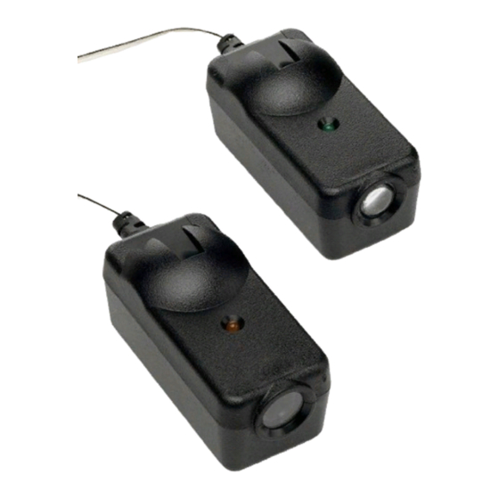
SAFETY REVERSING SENSOR REPLACEMENT
WALL OPTION
Make sure the brackets on each side are clear of the door track and have the same
amount of clearance so the sensors will align correctly. If additional clearance is needed,
use extension brackets 041A5281-1 (not provided) or wood blocks.
1. Attach the sensor bracket against the wall with two lag screws (not provided).
2. Slide the hex screw through the sensor.
3. Attach the sensor to the bracket with the wing nut. Make sure the lens is not
obstructed by the bracket.
Repeat the steps with the other sensor on the opposite side of the garage door. Both
lenses must face each other.
1
Door track
2
FLOOR OPTION
1. Measure the position of both sensor brackets so they will be the same distance
from the wall and unobstructed.
2. Attach the bracket to the floor with concrete anchors (not provided).
3. Slide the hex screw through the sensor.
4. Attach the sensor to the bracket with the wing nut. Make sure the lens is not
obstructed by the bracket.
Repeat the steps with the other sensor on the opposite side of the garage door. Both
lenses must face each other.
1
Wing nut
Door track
3
Inside
garage wall
Not provided
3
Inside
2
garage wall
4
041-0136 & 041-0155
OPTIONAL
OR
Wing Nut
6" (15 cm)
max.
Not provided
Wingnut
6" (15 cm) max.
Advertisement

Related Manuals for Chamberlain 041-0136

Summary of Contents for Chamberlain 041-0136
- Page 1 SAFETY REVERSING SENSOR REPLACEMENT 041-0136 & 041-0155 WALL OPTION Make sure the brackets on each side are clear of the door track and have the same amount of clearance so the sensors will align correctly. If additional clearance is needed, use extension brackets 041A5281-1 (not provided) or wood blocks.
-
Page 2: Test The Sensors
WIRE THE SENSORS TEST THE SENSORS 1. Separate the ends of the new sensor wire. Cut any exposed wire down to the insulation. 2. Using the four locking connectors, connect the new wire to the existing wire by color: white/black to white/black, white to white. NOTE: If installing in a pre-wired Without a properly installed safety reversing sensor, persons (particularly small garage, connect the new sensor wires to the same pre-installed wires as the old children) could be SERIOUSLY INJURED or KILLED by a closing garage door. - Page 3 REMPLACEMENT DU CAPTEUR D’INVERSION DE SÉCURITÉ 041-0136 ET 041-0155 OPTION MURALE S’assurer que les supports de chaque côté sont dégagés du guide de la porte à la même distance de sorte que les capteurs sont alignés correctement. Si un dégagement supplémentaire est nécessaire, utiliser les supports de rallonge 041A5281-1 (non...
-
Page 4: Dépannage
CÂBLAGE DES CAPTEURS ESSAI DES CAPTEURS 1. Séparer les extrémités du fil du capteur neuf. Couper tout fil exposé jusqu’à la gaine isolante. 2. Avec quatre connecteurs à verrouillage, connecter le nouveau fil au fil existant par couleur : Blanc / noir à blanc / noir, blanc à blanc. REMARQUE : Pour une Sans un système d’inversion de sécurité... - Page 5 REPUESTO DEL SENSOR DE REVERSA DE SEGURIDAD 041-0136 Y 041-0155 OPCIÓN DE PARED Asegúrese de que las ménsulas de cada lado no queden obstaculizadas por los rieles de la puerta y tengan el mismo espacio libre para que los sensores se alineen correctamente.
- Page 6 CONECTAR LOS SENSORES PROBAR LOS SENSORES 1. Separe los extremos del cable del sensor nuevo. Corte cualquier cable expuesto hasta el aislamiento. 2. Utilizando los cuatro conectores de fijación, conecte el cable nuevo al cable existente por color: blanco/negro a blanco/negro, blanco a blanco NOTA: Si realiza Si un sensor de reversa de seguridad no se ha instalado adecuadamente, las la instalación en un garaje precableado, conecte los cables del sensor nuevo a los personas (y los niños pequeños en particular) podrían sufrir LESIONES GRAVES o...
- Page 8 © 2021, The Chamberlain Group, Inc. All Rights Reserved The Chamberlain Group, Inc. Tous droits réservés 300 Windsor Drive 114-5568-000 Todos los derechos reservados Oak Brook, IL 60523...