Table of Contents
Advertisement
Quick Links
APPLICABLE PARTS (SOLD SEPARATELY)
•
SA310KR
INTRODUCTION
This kit contains everything needed for rapid prototyping with the SA310KR 3-phase driver. With a multi-
tude of circuit options, the EK76 offers versatility when in comes to connecting inputs, measuring outputs,
and conditioning signals to the specific application environment. High- and low- input signals for each phase
may be supplied from any 3 V to 18 V digital controller via standard pin header or SMA connectors. A remov-
able 50 Ω termination resistor is offered for impedance-matched inputs. Coaxial measurement points are
offered for high-fidelity waveform measurement, so erroneous overshoot/ringing are cut down to a mini-
mum. The layout is carefully optimized for signal and power transmission, while permitting easy integration
with system controllers and 3-phase loads.
ABSOLUTE MAXIMUM RATINGS
All specifications listed in the SA310 datasheet apply to this board, except as noted below. This board
uses components that limit SA310's full operating range in exchange for convenience to the customer.
Parameter
Output Current, continuous, within SOA
Power Dissipation, SA310
www.apexanalog.com
Subject to Change
Evaluation Kit
Symbol
Max
I
OUT
P
D
© Apex Microtechnology Inc.
All rights reserved
EK76
Units
20
A
60
W
Limited By
DUT-socket
DUT-HS
May 2020
EK76U Rev A
Advertisement
Table of Contents

Subscribe to Our Youtube Channel
Related Manuals for Apex Digital EK76

Summary of Contents for Apex Digital EK76
- Page 1 This kit contains everything needed for rapid prototyping with the SA310KR 3-phase driver. With a multi- tude of circuit options, the EK76 offers versatility when in comes to connecting inputs, measuring outputs, and conditioning signals to the specific application environment. High- and low- input signals for each phase may be supplied from any 3 V to 18 V digital controller via standard pin header or SMA connectors.
- Page 2 EK76 Figure 1: Circuit Diagram CURRU BIAS GNDU IMONU BIAS BIAS IMONW IMONV GNDW GNDV CURRV CURRW CBP4 OPTIONAL CURRENT SENSE CIRCUIT CBP2 CBP3 LED1 CBP5 CBP1 PGND_W socket INW_HS OUT_W INW_LS +VS_VW PGND INW_H INV_HS OUT_V INW_L INV_LS PGND_V...
-
Page 3: Parts List
EK76 PARTS LIST Reference Manufacturer Part # Description Printed Circuit Board EVAL94 EVAL94 Printed Circuit Board Resistors R1, 2, 3 CSR03 Res, 10mΩ, 16W, 5%, TO-220 R4,5 CFR-50JB-52-430K Res, 430kΩ, 1/2W, 5%, Axial 4610X-101-510LF Res, 9 array, 51Ω, 0.2W, SIP... - Page 4 EK76 Optional Components (Not Included) P6-14 CON-SMA-EDGE-S SMA Connector LM6134BIN/NOPB Quad Op Amp, 14 DIP through hole C1, 2, 3 CAP 0805 Not Populated C0805C104M5RACTU CAP 0805 100nF 50V X7R R9, 12, 13, 16, 17, 20 ERA-6AEB4992V RES 0805 49.9kΩ 1/8W 0.1%...
-
Page 5: Before You Get Started
EK76 BEFORE YOU GET STARTED • All Apex Microtechnology amplifiers should be handled using proper ESD precautions. • Always use the heat sink included in this kit. • Always use adequate power supply bypassing. • Do not change the connections while the circuit is powered. -
Page 6: Motor Control
Applications requiring torque control will require the Current Sense gain and off- set circuit described below. Use default values when pairing with the Juno device. Other motor control ICs may be used with EK76, but these may require different wiring and/or current sense circuits. -
Page 7: Current Sense
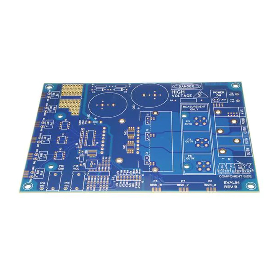
C1, 2, 3 1 / (2π * f After assembly of the EK76 including the above Current Sense circuit, R22 must be trimmed to reach the desired value of V . To do this, attach a Voltmeter to measure the voltage between pins 11 (negative) and 13 (positive) of P2. - Page 8 EK76 Figure 2: Top View EK76U Rev A...
- Page 9 EK76 Figure 3: Bottom View EK76U Rev A...
-
Page 10: Test Setup
EK76 TEST ASSEMBLY EQUIPMENT NEEDED 1. Power Supplies 2. Digital Controller or 6+ Channel Pattern Generator 3. Oscilloscope 4. Proper Heatsinking System TEST SETUP Make sure all supplies are turned off before connection. Connect the power supplies V (via P15 and P16) and +V (via P1).
Need help?
Do you have a question about the EK76 and is the answer not in the manual?
Questions and answers