Table of Contents
Advertisement
Quick Links
Advertisement
Table of Contents

Related Manuals for DEWESOFT VIBRO KIT V20-2

Summary of Contents for DEWESOFT VIBRO KIT V20-2
- Page 1 VIBRO KIT TECHNICAL REFERENCE MANUAL VIBRO KIT V20-2...
-
Page 2: Table Of Contents
7.7 Trademarks 8 Safety instructions 8.1 Safety symbols in the manual 8.2 General Safety Instructions 8.2.1 Environmental Considerations 8.2.2 Product End-of-Life Handling 8.2.3 System and Components Recycling 8.2.4 General safety and hazard warnings for all Dewesoft systems VIBRO KIT V20-1 2/29... - Page 3 VIBRO KIT TECHNICAL REFERENCE MANUAL 9 Documentation version history VIBRO KIT V20-1 3/29...
-
Page 4: About This Document
VIBRO KIT TECHNICAL REFERENCE MANUAL 2 About this document 2.1 Legend The following symbols and formats will be used throughout the document. Important It gives you important information about the subject. Please read carefully! Hint It gives you a hint or provides additional information about a subject. Example Gives you an example of a specific subject. -
Page 5: Technical Data
VIBRO KIT TECHNICAL REFERENCE MANUAL 3 Technical data 3.1 Introduction The new VIBRO-KIT is a compact tool for simulating rotating machinery measurements. It is meant for demonstrations or educational purposes such as in a lab or university. It provides a playground for almost unlimited experiments. -
Page 6: Vibro-Kit Parts Description
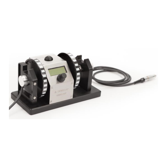
VIBRO KIT TECHNICAL REFERENCE MANUAL 3.3 Vibro-kit parts description 3.3.1 Encoders Using projection below the left side refers to the Tacho 1 output signal and right side refers to the Tacho 2 output signal. Image 1: Vibro-kit unit Counter input connectors on cable Name Description IN0/A... -
Page 7: Optical Sensor Below Taped Disk
VIBRO KIT TECHNICAL REFERENCE MANUAL 3.3.2 Optical sensor below taped disk Integrated optical sensor on the bottom side of the chassis for measuring signal of the striped tape on the rotating disc which is affixed on the shaft of the motor. Please see chapter 3.3.1. -
Page 8: Front Panel
VIBRO KIT TECHNICAL REFERENCE MANUAL 3.3.3 Front panel Button on the top serves as a ON/OFF start button for the motor. The front knob serves as a navigation knob for the Menu. Display shows general values and motor options when Vibro-kit is turned on. Image 3: Front panel of drive part VIBRO KIT V20-1 8/29... -
Page 9: Back Panel
VIBRO KIT TECHNICAL REFERENCE MANUAL 3.3.4 Back panel Image 4: Back panel of drive part Power supply connector Name Description Power supply 12V...36V Ground VIBRO KIT V20-1 9/29... - Page 10 VIBRO KIT TECHNICAL REFERENCE MANUAL Control IN connector Using an input signal if you want to control the RPM of an internal motor with voltage signal. BNC female connector Tacho 1 Out Measuring an output signal from an optical sensor that is integrated below the rotating disk. BNC female connector Tacho 2 Out Measuring an output signal from an optical...
-
Page 11: Couplings
VIBRO KIT TECHNICAL REFERENCE MANUAL 3.3.5 Couplings The right encoder is connected to the spring coupling which damps high accelerations but may cause an oscillation until the moving parts are equalized. Black round plate has a white dotted strap on it which you can read with the tacho sensor. Image 5: Flexible coupling on the right side The left encoder is connected to the rigid coupling which eliminates any oscillations in regard to the accelerating. -
Page 12: Possibilities Of Use
VIBRO KIT TECHNICAL REFERENCE MANUAL 4 Possibilities of use 4.1 Super-counters Additional equipment: SIRIUS with at least one CNT module (ACC+, …). DewesoftX’s super-counters work on a 102.4 MHz internal time base, always, independent of the current sample rate. In comparison to standard counters, which only output whole numbers like 1,1,2,2,3,4, … one sample later, DewesoftX ®... - Page 13 VIBRO KIT TECHNICAL REFERENCE MANUAL Image 8: Counters In the Counter menu, you will see all the available counter channels. Enter the setup of the channel where your encoder is connected. Change the Basic application to the Sensor and choose the correct sensor from the dropdown list. If your sensor is not on the list, you can add it in the counter sensor editor.
- Page 14 VIBRO KIT TECHNICAL REFERENCE MANUAL Image 9: Counter menu Enter the Measure mode and add a recorder visual control. Display the Angle and Raw count on the same recorder. When the Vibro Kit is running, press Freeze and zoom into the signal. You can see how DewesoftX ®...
-
Page 15: Fft Analyzer
TECHNICAL REFERENCE MANUAL Image 10: Signals on recorder For more detailed explanation of the parameters, please visit: https://training.dewesoft.com/online/course/digital-counters 4.2 FFT analyzer Additional needed equipment: SIRIUS with one ACC, accelerometer. Glue the accelerometer on the Vibro Kit. Connect the accelerometer to the SIRIUS ACC module, and enter the channel setup. - Page 16 VIBRO KIT TECHNICAL REFERENCE MANUAL Image 12: FFT analyser settings Enter the measure mode and add the FFT channel on a 2D graph. Run the machine and observe the FFT. Image 13: FFT math on 2D graph VIBRO KIT V20-1 16/29...
-
Page 17: Order Tracking
On the FFT graph, you can show the markers and how FFT behaves with different parameters in the setup. For an explanation of all the parameter visit: https://training.dewesoft.com/online/course/fft-spectral-analysis 4.3 Order tracking Additional needed equipment: SIRIUS with one ACC and one CNT module, accelerometer. -
Page 18: Balancing
VIBRO KIT TECHNICAL REFERENCE MANUAL The order tracking module creates a display with two 3D graphs to show order and FFT waterfalls, two 2D graphs to show the order harmonics and phase of the harmonics and a digital meter to monitor the RPMs of the machine. - Page 19 From those two unbalanced vectors, we calculate the correction mass that has to be added and the angle at which this should be added. You can perform as many steps as you wish. Image 17: Rotor balancer screen For more detailed explanation of balancing parameters and settings, please visit: https://training.dewesoft.com/online/course/balancing VIBRO KIT V20-1 19/29...
-
Page 20: Torsional Vibration
Select the wanted output channel from the module. Detailed description of the parameters and setting can be found here: https://training.dewesoft.com/online/course/rotational-and-torsional-vibration Image 18: Torsional vibration settings Enter the measure mode. The plugin creates a new display with 2 XY recorders for displaying the rotational angles and torsional angle against the reference angle sensor. - Page 21 VIBRO KIT TECHNICAL REFERENCE MANUAL Image 19: Torsional vibration screen VIBRO KIT V20-1 21/29...
-
Page 22: Specifications Hw V1.3
VIBRO KIT TECHNICAL REFERENCE MANUAL 5 Specifications HW v1.3 Parameter Value Unit Power supply Input Voltage 10 … 26 Power supply Input Current Limit Control Input Voltage range (Analog 0 … 10 mode) Control Input Voltage levels (PWM TTL (3,3V or 5V) mode) Control Input Frequency max (PWM mode) -
Page 23: Ramp Mode
VIBRO KIT TECHNICAL REFERENCE MANUAL Motor Voltage (V) Motor Speed (RPM) 1,00 2,00 1100 3,00 1800 4,00 2300 5,00 3000 To exit Manual mode, disable motor first, then hold ENC_SW for 1sec. ● Enabling the motor after the motor voltage has been set too high may result in input current ●... -
Page 24: Analog In Mode
VIBRO KIT TECHNICAL REFERENCE MANUAL Enable motor and start Ramp cycling by holding RUN_SW for 1 sec. Number of cycles remaining ● is now shown in bold font. Arrow is also shown in bold and shows the current step of ramp cycle. Parameters are updated live during runtime to show progress. -
Page 25: Warranty Information
7.2 Support Dewesoft has a team of people ready to assist you if you have any questions or any technical difficulties regarding the system. For any support please contact your local distributor first or Dewesoft directly. -
Page 26: Printing History
When used in text representing the company, product or technology name, the ® sign is not used. The Dewesoft triangle logo is a registered trademark but the ® sign is not used in the visual representation of the triangle logo. -
Page 27: Environmental Considerations
This symbol indicates that this system complies with the European Union’s requirements according to Directive 2002/96/EC on waste electrical and electronic equipment (WEEE). Please find further information about recycling on the Dewesoft web site www.dewesoft.com Restriction of Hazardous Substances This product has been classified as Monitoring and Control equipment and is outside the... - Page 28 REMOVE POWER and do not use the product until the safe operation can be verified by service-trained personnel. If necessary, return the product to the Dewesoft sales and service office for service and repair to ensure that safety features are maintained.
- Page 29 VIBRO KIT TECHNICAL REFERENCE MANUAL Do not switch on the system after transporting it from a cold into a warm room and vice versa. ● The thereby created condensation may damage your system. Acclimatize the system unpowered to room temperature. Do not disassemble the system! There is a high risk of getting a perilous electric shock.
Need help?
Do you have a question about the VIBRO KIT V20-2 and is the answer not in the manual?
Questions and answers