
Related Manuals for DataOn Storage CiB-9224 V12

Summary of Contents for DataOn Storage CiB-9224 V12
- Page 1 CiB-9224 Tech Manual Version Jun. 2015 © DataON Storage, storage division of Area Data Systems.
- Page 2 DataON Storage. Trademarks All product names or brands mentioned herein are the trademarks of DataON Storage, its subsidiaries or other respective owners in United States and other countries. Disclaimer This manual provides the information in relation to the set-up and installation of the product herein.
-
Page 4: Table Of Contents
Contents About This Manual ........................i Conventions .............................. i Safety Symbols ............................. ii Safety Precautions ..........................iii Regulatory and Integration Information ....................vii Rack Mount Instructions ........................x Introduction ........................1-1 Audience Assumptions ......................1-1 Manual Organization ......................1-1 Specifications ......................... 1-1 Product Features ........................ -
Page 6: About This Manual
About This Manual Conventions Safety Symbols Safety Precautions Regulatory and Integration Information Rack Mount Instructions... - Page 8 Information to prevent injury to yourself when trying to complete a Warning: task. Information to prevent damage to the components when trying to Caution: complete a task. Important: Information that you must follow to complete a task. Note: Tips and information to aid in completing a task. CiB-9224 V12...
- Page 9 Warning: To reduce the risk of personal injury or damage to the equipment, Weight in kg. observe local occupational health and safety requirements and guidelines for Weight in lb. manual material handling. CiB-9224 V12...
- Page 10 Any defected components, do not try to fix it by yourself. Contact an authorized dealer. Gloves are recommended when handling server to protect from cuts and scrapes. When server is powered on, components maybe hot. Proceed with caution. Check whether fans are functioning properly. CiB-9224 V12...
- Page 11 This server is provided with an internal Lithium battery or battery pack. There is a danger of explosion and risk of personal injury if the battery is incorrectly replaced or mistreated. For more information about battery replacement or proper disposal, contact an authorized reseller or your authorized service provider. CiB-9224 V12...
- Page 12 The suitability of this product for other product categories and environments (such as medical, industrial, residential, alarm systems, and test equipment), other than an ITE application, may require further evaluation. CiB-9224 V12...
- Page 13 Clean, dry, and free of airborne particles (other than normal room dust). Well-ventilated and away from sources of heat including direct sunlight and radiators. Vibration or physical shock free environment. Provided with a properly grounded wall outlet. CiB-9224 V12...
- Page 14 Many electronic devices, including computers, generate RF energy incidental to their intended function and are, therefore, covered by these rules. These rules place computers and related peripheral devices into two classes, A and B, depending upon CiB-9224 V12...
- Page 15 Compliance with these directives implies conformity to the following European Norms (in brackets are the equivalent international standards): Table ii European Union EMC Requirements EN55022 (CISPR 22) Electromagnetic Interference EN55024 (IEC61000-4-2,3,4,5,6,8,11) Electromagnetic Immunity EN61000-3-2 (IEC61000-3-2) Power Line Harmonics EN61000-3-3 (IEC61000-3-3) Power Line Flicker viii CiB-9224 V12...
- Page 16 1.00mm² or 18AWG, and the length of the cords must be between 1.8m (6 feet) and 3.6m (12 feet). If you have questions about the type of power cord to use, contact an authorized service provider. CiB-9224 V12...
- Page 17 System placement – System must be place on a leveled surface. Circuit Overloading – To avoid power supply overload, make sure main power source is adequate to accommodate all system. CiB-9224 V12...
-
Page 18: Introduction
About This Manual Chapter 1 Introduction Audience Assumptions Manual Organization Specifications Product Features System Overview... - Page 19 1.1 Audience Assumptions This document is for the person who installs, administers, and troubleshoot storage systems. DataON Storage assumes you are qualified in the servicing of this equipment and trained in recognizing hazards in products with hazardous energy levels. 1.2 Manual Content For your informations, chassis and hardware specification is provided.
-
Page 20: Product Features
24 x 2.5” hot-pluggable HDDs (Front) Storage 2 x 2.5” SSDs (Rear) One 2.5” HDD Backplane Backplane Two Boot SSD backplanes Number of fan cage: 4 System Fan Single Fan Size: 60mm x 60mm x 38mm CiB-9224 V12... -
Page 21: System Overview
Nodes Power Distribution Boards BBU Assembly (BBU + Fan Duct) Strong Plate Middle Plane Bridge Board Front Panel 2 Front Panel 1 HDD Bays 2.5” HDD Backplane System Fans Boot SSD Assembly Expansion Card Assembly (Low Profile) CiB-9224 V12 ... -
Page 22: Front View
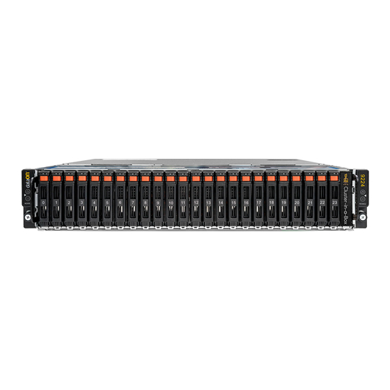
Introduction 1.5.2 Front View CiB-9224 V12 supports up to 24 x 2.5” HDD configurations. The 2U server allow front access to the HDD. In addition, systems LEDs indicators is also located on the front for easy notification. Figure 1-3 Front View of 24 x 2.5”... -
Page 23: Back View
11 10G NIC 1 Link / Activity LED 12 10G NIC 1 Speed LED 13 10G NIC 0 Speed LED 14 Power Button 15 JBOD HDMini-SAS Connector 3-4 16 JBOD HDMini-SAS Connector 1-2 17 JBOD Power LED CiB-9224 V12 ... -
Page 24: Buttons And System Led Information
ID of each node. Figure 1-5 Front Panel Buttons and LEDs 1 ID Button for Node 1 2 Power Button for Node 1 3 ID Button for Node 2 4 Power Button for Node 2 CiB-9224 V12... - Page 25 Amber (IPMI) Via chassis identify command on or ID button press ID on (IPMI) Via chassis identify ID LED Blue command off or ID button press ID off Only (IPMI) Via chassis identify Blink command blink on CiB-9224 V12 ...
-
Page 26: Motherboard Connectors
Motherboard Connectors 1.5.5 Figure 1.6 Motherboard Overview CiB-9224 V12... - Page 27 Power Connector (J64) DIMM Slots for Processor 1 (C0, C1, D0, D1) Processor 1 (CPU1) System Battery (BH1) Processor 0 (CPU0) DIMM Slots for Processor 0 (A0, A1, B0, B1) PCI-e x8 Slot for LSI SAS 3008 CiB-9224 V12 ...
-
Page 28: Hardware Operations
Chapter 2 Hardware Operations Before You Start Chassis Cover Power Supply 2.5” SAS HDDs Nodes SAS I/O Module Boot HDD X16 Riser Card BBU (optional) System Fans... -
Page 29: To Remove The Chassis Cover
2.2.1 To remove the chassis cover Release the screw on the chassis cover. Press the button along the direction of the arrow. Simultaneously slide the cover horizontally to the back and remove it. Figure 2-1 Removing the Chassis Cover CiB-9224 V12... -
Page 30: To Install The Chassis Cover
Locate the chassis cover to the right position on the chassis as shown below and then slide it to the front until it is closed. Figure 2-2 Sliding the Chassis Cover to the Front Secure the chassis cover with one screw. Figure 2-3 Tightening the Screw CiB-9224 V12... -
Page 31: Power Supplies
To ensure proper cooling. Chassis cover must be install before turning on the system. 2.3 Power Supplies CiB-9224 V12 offer two 1200w hot-swappable redundant power supplies. If one power supply fail, simply replace the power supply module without powering off the system. -
Page 32: To Install The Power Supply
Installing the Power Supply 2.4 2.5” SAS HDDs The CiB-9224 V12 support up to 24 x 2.5” hot-pluggable SAS HDD / SSD. You don’t need to power-off the system when removing or installing a HDD / SSD. The location of 2.5” SAS HDD / SSD assemblies on the server is shown below:... -
Page 33: To Remove A Hdd
Slide the HDD / SSD assembly out of the Drive bay. Figure 2-8 Sliding out the HDD Assembly Loosen the four screws that secure the HDD / SSD. Lift the HDD / SSD out of the Drive tray. CiB-9224 V12 ... -
Page 34: To Install A Hdd
2.4.2 To install a HDD / SSD Place the HDD / SSD to the Drive tray. Figure 2-10 Placing the HDD / SSD to the Drive Tray Secure the HDD / SSD to the Drive tray with four screws. Figure 2-11 Fastening the Screws CiB-9224 V12... -
Page 35: Nodes
Installing the HDD Assembly Make sure that the HDD / SSD is connected to the Drive connector on the backplane. 2.5 Nodes CiB-9224 V12 system supports two nodes. The location of node on the system is shown below: Figure 2-13... -
Page 36: To Remove The Node
Push the node into the chassis until it’s completely seated in place. Secure the screw. Figure 2-15 Installing the Node 2.6 SAS I/O Module The CiB-9224 V12 supports two JBOD modules. The location of JBOD module on the system is shown below: CiB-9224 V12... - Page 37 Slide the JBOD assembly out of the chassis by using the lever. Figure 2-17 Removing the JBOD Assembly When install the JBOD assembly: Please mind fingers between the lock hinge and tray as it may cost injuries CiB-9224 V12 ...
-
Page 38: Boot Ssd
Make sure the server is turned off and disconnected to any AC power source. Pull the SSD assembly out of SSD cage. Figure 2-18 Removing the SSD Assembly Remove the SSD out of the SSD tray along the direction of the arrow. Figure 2-19 Removing the HDD 2-10 CiB-9224 V12... -
Page 39: X16 Riser Pci-E Card
Loosen the screws that secure the expansion card. Remove the expansion card. Install the expansion-card slot cover. Figure 2-21 Removing the Expansion Card 2.8.3 To install the expansion card Reverse the steps above to install the expansion card. 2-11 CiB-9224 V12 ... -
Page 40: Bbu Assembly For Raid Controller (Optional)
2.9.1 To remove a BBU Remove a BBU out of the BBU assembly along the direction of the arrow. Figure 2-22 Removing the BBU 2.9.2 To install a BBU Reverse the steps above to install a BBU. 2-12 CiB-9224 V12... -
Page 41: Air Duct
Subdividing the node area and the backplane area is a metal cage that holds the system fans. This CiB-9224 V12 contains four system fans which are located inside the chassis. These system fans maintain the ideal temperature for the node, backplane and disk drives. -
Page 42: To Remove A System Fan
Disconnect all the necessary cables. 2.11.1 To remove a system fan Lift a system fan out of the chassis directly. Figure 2-25 Removing a System Fan 2.11.2 To install a system fan Reverse the step above to install a system fan. 2-14 CiB-9224 V12... - Page 43 [Type here] Appendix China RoHS Regulations...
-
Page 44: Appendix China Rohs Regulations
Hardware Operations Appendix Appendix China RoHS Regulations Figure I China RoHS Regulations CiB-9224 V12...
Need help?
Do you have a question about the CiB-9224 V12 and is the answer not in the manual?
Questions and answers