Table of Contents
Advertisement
Quick Links
Advertisement
Table of Contents

Related Manuals for Linkam Scientific Instruments FTIR600


Summary of Contents for Linkam Scientific Instruments FTIR600
- Page 1 Linkam Scientific Instruments FTIR600 Temperature Controlled IR Stage USER GUIDE...
-
Page 2: Table Of Contents
Introduction..........................6 FTIR600 Stage Specification..................6 FTIR600 System........................6 Stage Anatomy........................7 FTIR600 Stage Assembly……..…………..…………………………………………………………………..7 Stage Assembly......................7 Lid Assembly......................7 FTIR600 Vertical Stage Anatomy………………………………………………………………………………8 Window Assembly.........................9 Lid Window Assembly....................9 Bottom Window Assembly..................9 Mounting Stage to an Optical FTIR Microscope…………............10 Vacuum Tweezers.......................11 Connecting the Instruments....................12 T95 System Controller Cable Connections................12 LNP95 Cooling Pump Connection..................12... -
Page 3: Before Setting Up Your Equipment
Before Setting Up Your Equipment Please register your products by going to www.linkam.co.uk and click on the product/software registration button. You will need to register your equipment with us to: Activate your warranty and technical support Access the online setup videos ... -
Page 4: Important Notice
Important Notice Please check that your Linkam equipment has not been damaged during transit. If there is any evidence of external damage DO NOT SWITCH ON ANY ELECTRICAL ITEMS. Contact LINKAM SCIENTIFIC or their appointed distributor immediately. Your warranty may be im- paired if Linkam is not informed of any transport damage within 7 working days of delivery. -
Page 5: Safety Precautions
Safety Precautions Read this guide before using the equipment. Save these instructions for later use. Follow all warnings and instructions which may be placed on the programmer or stage. If for any reason the mains fuse needs to be replaced then it must be replaced by one of the same type and rating as shown in the equipment ratings. -
Page 6: Introduction
3mm or 1.3mm Weight: 0.6Kg FTIR600 System The system consists of a FTIR600 stage, a T95- LinkPad System Controller and optional LNP95 liquid nitrogen cooling pump. Linksys32 System control software and digital video capture can be added as an option to control from a PC. -
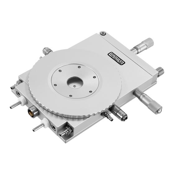
Page 7: Stage Anatomy
Stage Anatomy FTIR600 Stage Assembly 1. Lemo connector for stage lead 2. Heating element carrier assembly 3. Stage body 4. Stage body water connector 5. Gas purge valve 6. Y-Sample manipulator 7. Stage door 8. Door locking thumbscrew 9. X-Sample manipulator 10. -
Page 8: Ftir600 Vertical Stage Anatomy
FTIR600 Vertical Stage Assembly The FTIR600 Vertical Stage has the same specifi- cations and works in exactly the same way as the standard FTIR600. The heater assembly is locat- ed on the side, the Gas Purge Valve and Stage body water cooling connectors are repositioned so... -
Page 9: Window Assembly
Window Assembly A standard Quartz window is fitted in the top and bottom window of the FTIR600 Stage. If you have ordered alternative IR transparent windows (potassium bromide, calcium fluoride, barium flouride), please follow the instruction below to exchange the windows. -
Page 10: Mounting Stage To An Optical Ftir Microscope
Mounting Stage to an Optical FTIR Microscope The following description is for mounting the 9542 curved clamps set FTIR600 Stage on to an optical FTIR micro- scopes which have a circular substage assembly (1). Attach the curved stage clamps (part no. 9542) to the base of the stage using the supplied hex screws and the outer most holes in the base plate. -
Page 11: Vacuum Tweezers
Vacuum Tweezers The vacuum tweezers are used to manipulate the glass sample slides onto the silver block to pre- vent fingerprints on the glass and scratching the surface of the silver block when using standard fine tip metal tweezers. The System is supplied with a Vacuum Tweezers Kit which consists of a Vacuum Pump (1) and tweezers (2). -
Page 12: Connecting The Instruments
Connecting The Instruments T95 System Controller Cable Connections T95 back panel For more details on the T95 System Controller please refer to the T95 System Controller manual. Connect the Stage Cable to the Lemo Connector on the stage and connect the other end to the Stage Connection Socket (1). -
Page 13: Ecp Water Circulator Pump
ECP Water Circulator Pump If you have purchased the ECP with your System, read the following to set up the ECP with the FTIR600 stage. Refer to the ECP manual for more details. When heating the stage above 300°C for a pro- longed period of time, the metal casing body of the stage can get quite hot. -
Page 14: Sample Preparation
Sample Preparation FTIR/CC Sample Carrier and Stain- less Steel Ring To load the FTIR/CC Crucible Holder (1). Open the side door of the stage with the thumb- screw and slide the FTIR/CC Sample Holder (1) in. Push the holder as far as it will go, close the door and tighten the thumbscrew to seal the stage. - Page 15 Use the vacuum tweezers or a pair of tweezers as shown and place a 16mm Sample Window (1) into the stainless steel ring. Tap the edges lightly to ensure that it sits flat against the surface of the block. The Stainless Steel Ring is used to push the 16mm cover slip around the surface of the block when using the XY manipulators.
-
Page 16: Cooling Connections
Cooling Connections These connections need only be made if the experiments are to be carried out below room temperature. The Dewar siphon (1) is the thick white foam tubing and is attached to the liquid nitrogen Dew- ar. The thin black capillary tube inside the white foam tube must be inserted into the liquid nitro- gen cooling connectors on the stage. -
Page 17: Purging Procedure
Purging Procedure Before starting a cooling experiment, you will need to purge air from the stage chamber with dry nitrogen. This will remove the water in the air which would otherwise condense and freeze on the sample disrupting your image quality and giving you an unwanted O-H between 3000-3600cm Before you can start purging, the LNP95 must be set to manual mode. -
Page 18: Purging The Stage Method 1
Purging the Stage Method 1 There are two methods for purging the stage. Method 1 uses recycled nitrogen gas produced by the LNP95 from the 2L Dewar. Make sure the stage lid is in place and the stage door is closed. Switch on the temperature programmer and set the limit to 40°C. -
Page 19: Purging The Stage Method 2
Purging the Stage Method 2 This method uses an inert gas from a gas cylinder to purge the stage at temperatures above ambient when the LNP95 is not required. 1. Make sure the Stage Lid is in place and the Stage Door is closed. -
Page 20: Ftir600 Vertical Stage
The vertical sample holder is used to keep the sample in place. The FTIR600 Vertical Stage has the same specifi- cations and works in exactly the same way as the standard FTIR600. The heater assembly is locat-... -
Page 21: Ftir600 Vertical Stage Setup
FTIR600 Vertical Stage Setup Gas Purge Valve with Tubing Connection The Stage is sent out with Gas Purge Valve with Tubing (1) disconnected. To connect the Gas Purge Valve with Tubing, use one hand to hold the black and blue colour gas valve (2), then firmly and push the tubing into the hole as far it can go. -
Page 22: Base Stand Assembly
Base Stand Assembly Fix the Stand Assembly to the Stage using the two screws (1) to the two holes (2) on the bottom of the Stage as shown in the opposite diagram. Note: Make sure the two spacers (3) are placed between the Base Stand (4) and the Stage. -
Page 23: Sample Preparation
Sample Preparation With the Lid off and the stage lying flat on a flat surface. Place a 16mm IR Transparent Sample Window on the silver block. Place the sample on top of the 16mm Sample window. Note: if the sample is less than 10mm in diameter you must place another 16mm IR Transparent Window over the sample. - Page 24 Insert the peg (1) of Sample holder into the hole (2) of Sample Holder Post. Once the Sample Holder is inserted use a finger to push the Sample Holder firmly into the Sample Holder Post. The spring action of Sample Holder will keep the sample in place when the Stage is standing up vertically.
-
Page 25: Appendix
The FTIR600 heating element is extremely durable if used carefully. However, it is made from pure silver which is a soft metal. It can be easily scratched, which will compromise the heat flow to the sample and Part No. - Page 26 Spares and Accessories Part No. Part Name Part Description FTIR600 22222 ZnSe Kit Full Replacement ZnSe Spares Kit (0.5mm) (0.5mm) W10Z 0.5 Zinc Selenide Sample Window 10mm diameter 0.5mm thick x2 W16Z 0.5 Zinc Selenide Sample Window 16mm diameter 0.5mm thick x2 W22Z 0.5...
- Page 27 Spares and Accessories FTIR600 22222 Full Replacement KBr Spares Kit KBr Kit W10K Potassium Bromide Sample Window 10mm diameter 0.5mm thick x2 W16K Potassium Bromide Sample Window 16mm diameter 0.5mm thick x2 W22K Potassium Bromide Lid/base Window 22mm diameter 1mm thick x2 Silicon Rings for Lid and Base (Set of 4 Part No.
-
Page 28: Troubleshooting
Troubleshooting Cooling fault diagnosis Ensure that all connections to the stage and Dewar are as described in the specific manual and that the stage lid and top windows are properly sealed. 1. The cooling rate is less than programmed. There can be several causes of this problem, the most likely being that one of the connectors has become blocked or damaged. - Page 29 This page is intentionally blank...
- Page 30 This page is intentionally blank...
- Page 31 This page is intentionally blank...
- Page 32 Linkam Scientific Instruments Ltd Tel: +44(0)1737 363 476 Fax: +44(0)1737 363 480 Email: support@linkam.co.uk Unit 8 Epsom Downs Metro Centre Waterfield, Tadworth, Surrey, KT20 5LR, UK www.linkam.co.uk Version: 1.01.0110...
Need help?
Do you have a question about the FTIR600 and is the answer not in the manual?
Questions and answers