Table of Contents
Advertisement
Advertisement
Table of Contents

Subscribe to Our Youtube Channel
Summary of Contents for Turbosol TB30
- Page 1 ORIGINAL USE AND MAINTENANCE MANUAL TB30 IS19/07 561405 Serial number Year...
-
Page 3: Table Of Contents
INDEX GENERAL INFORMATION ..................6 MACHINE IDENTIFICATION ......................7 DOCUMENTATION ACCOMPANYING THE MACHINE .............. 9 EC DECLARATION OF CONFORMITY (FACSIMILE) ............... 10 WARRANTY LIMITS ........................11 SPARE PARTS AND DUPLICATES OF DOCUMENTS ............. 11 INFORMATION FOR CONSULTATION ..................12 MACHINE PRESENTATION .................. 14 TECHNICAL DATA ........................ - Page 4 MAINTENANCE ..................... 66 ROUTINE MAINTENANCE ......................66 PREPARING THE MACHINE FOR LONG PERIODS OF INACTIVITY ........82 EXTRAORDINARY MAINTENANCE ................... 83 DEMOLITION ......................84 TROUBLESHOOTING ................... 86...
-
Page 6: General Information
GENERAL INFORMATION Dear Customer Congratulations on your purchase of a TURBOSOL machine. Our long experience, attention to the needs of users and the continuous technological research allow us to offer high quality machines, reliable and long-lasting. Even if you have used this type of machine before, it is extremely important to be informed on the operation and features by the TURBOSOL PRODUZIONE S.R.L. -
Page 7: Machine Identification
GENERAL INFORMATION MACHINE IDENTIFICATION 1.1.1 Machine orientation Front F, rear R, left side S and right side D refer to the running direction of the machine. 1.1.2 Machine plate The machine plate is affixed on the rear of the left side. It bears the following information: CE Marking Installed power Manufacturer’s company name and address... - Page 8 GENERAL INFORMATION 1.1.3 Machine serial number In addition to being indicated on the factory plate, the machine serial number is stamped on the chassis (Fig. 1-3). 1.1.4 Road trailer identification plate If the machine has been approved as road trailer, the identification data is shown in plate 1 positioned inside the bonnet, above the radiator.
-
Page 9: Documentation Accompanying The Machine
GENERAL INFORMATION 1.1.5 Vehicle’s identification number The vehicle's identification number is punched on the right-side front beam is present in the versions fitted with road approved tow, and repeated on the drawbar (FIG.1-6). DOCUMENTATION ACCOMPANYING THE MACHINE The machine is delivered with the following documentation: - Use and Maintenance Manual - EC Declaration of Conformity - S.P.C. -
Page 10: Ec Declaration Of Conformity (Facsimile)
GENERAL INFORMATION EC DECLARATION OF CONFORMITY (FACSIMILE) 10/87 561405 - IS19/07 - EN... -
Page 11: Warranty Limits
The goods supplied by Turbosol Produzione S.R.L. but manufactured by third parties are covered by the warranty granted by the latter to Turbosol and that is applied to the Final user. Only the Manufacturing Company and the Organisations expressly authorised by it can intervene in the event of faults during the warranty period. -
Page 12: Information For Consultation
GENERAL INFORMATION INFORMATION FOR CONSULTATION This paragraph contains information useful for the understanding of the text in this Manual. 1.6.1 Unit of measurement The I.S. (Internal System) has been adopted for the unit of measurement. SIZE UNIT DEFINITION ALTERNATIVE UNIT OF MEASUREMENT Time second min (minute, 1 min = 60 s), h (hour, 1 h=3600 s) - Page 13 GENERAL INFORMATION 13/87 561405 - IS19/07 - EN...
-
Page 14: Machine Presentation
MACHINE PRESENTATION MACHINE PRESENTATION TECHNICAL DATA ENGINE HATZ 3M41 Power 36.3 MAX/min speed 2400/1600 Cooling ENGINE PERKINS 404D-22 Power 36.3 MAX/min speed 2900/1550 Cooling Liquid ENGINE YANMAR 4TNV88-BDVF Power 36.4 MAX/min speed 3000/1500 Cooling Liquid ELECTRICAL SYSTEM Power voltage Fuse flow rate (on positive pole) Battery 12V 63Ah 610ccA HYDRAULIC SYSTEM... - Page 15 MACHINE PRESENTATION HIGH WASHER PRESSURE (Optional) Maximum pressure Rated flow rate l/min Maximum water temperature °C Minimum water temperature °C DIMENSIONS AND WEIGHTS Hopper Rated capacity Loading height 1510 Length With manual towing 4160 With tow on road 4500 Width With manual towing 1750 With tow on road...
-
Page 16: Type Of Machine
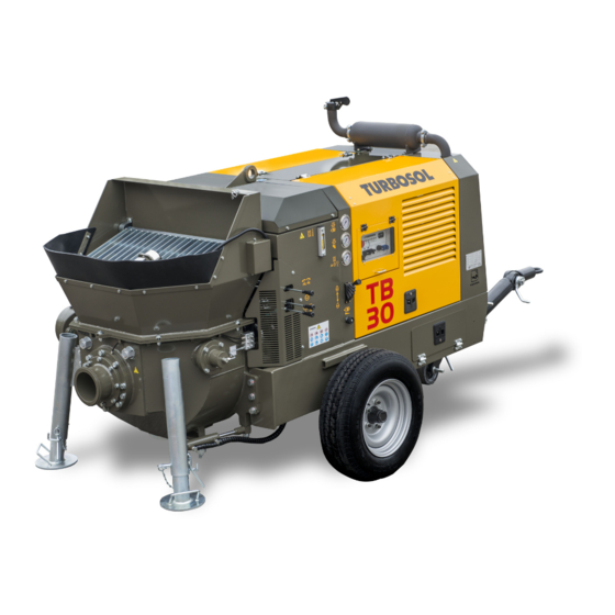
MACHINE PRESENTATION TYPE OF MACHINE The TB30 is a stationary machine for the distribution and projection of concretes and mortar. It is used autonomously and independently and is only intended for professional operators. OPERATION The machine's main unit is the pumping unit. It consists of a lower hopper (FIG.2-1-REF.1) housing the S valve (FIG.2-1- REF.2) and the mixer (FIG.2-1-REF.3). -
Page 17: Main Components Of The Machine
MACHINE PRESENTATION MAIN COMPONENTS OF THE MACHINE Hopper Controls Hopper grid Vibrator device Frame Outriggers Bodywork Trailer drawbar Discharge manifold Parking brake (as road trailer) Lifting ringbolt Wheel Engine cooling air socket Parking wedges Hopper agitator reducer Lights bar (as road trailer) Electric control board Plate housing (as road trailer) 17/87... - Page 18 MACHINE PRESENTATION Hydraulic pump Pumping cylinders Diesel engine, integrated in the machine No.2 S valve drive hydraulic actuators (see attached manual) Discharge silencer Lower hopper Hydraulic valve unit Hydraulic activation shutter for hopper discharge No.2 hydraulic pumping actuators Exchange S valve Lubrication water tank Product delivery manifold 18/87...
-
Page 19: Application Examples
MACHINE PRESENTATION APPLICATION EXAMPLES The machine is designed for transporting and pumping concrete (mixture of inert materials such as sand and gravel, binder such as cement, water in well defined proportions. The machine is able to pump the concrete if the mixture components are in such proportions to ensure smoothness along the pipe without creating segregations that clog the ducts. -
Page 20: Safety And Prevention
The contents of this Manual are protected by laws for intellectual property protection. It is forbidden to reproduce, store, duplicate, reprocess, disclose this Manual or parts thereof, with electronic systems or other types and in any form, without the prior written permission of TURBOSOL PRODUZIONE S.R.L. 20/87... -
Page 21: Recipients Of Use
SAFETY AND PREVENTION RECIPIENTS OF USE The machine was designed to be operated by the following professional figures: OPERATOR Person trained and informed on residual risks, who deals with the supervision and running of the machine. Must be trained on the position of all control and safety commands. - Page 22 SAFETY AND PREVENTION 1000 mm 1400 mm MAINTENANCE TECHNICIAN Qualified technical personnel in charge of the extraordinary maintenance of the machine. The maintenance technician is trained and informed on residual risks but with the safety skills of the maintenance personnel to whom the maintenance of the machine is entrusted, except for the internal combustion engine.
-
Page 23: Main Warnings
SAFETY AND PREVENTION MAIN WARNINGS The user is responsible for training operators and maintenance technicians and properly implementing the instructions provided. The use and maintenance of the machine are only permitted to professional, trained and authorised operators and maintenance technicians. The use of the machine is forbidden to people with disabilities and minors. -
Page 24: Special Warnings For The Work Phases
SAFETY AND PREVENTION Do not use open flames near the machine. Always have a first aid kit and fire extinguisher at hand. Observe the maintenance intervals indicated in chapter 6 of the Manual. Only use original spare parts. SPECIAL WARNINGS FOR THE WORK PHASES The following paragraphs take into consideration the residual risks present during the various work phases and the requirements to avoid them. - Page 25 SAFETY AND PREVENTION Observe the coupling angles of the ball joint: by overcoming these angles the components are excessively strained are the proper operation is no longer guaranteed (Horizontal ±20° and vertical ±25°). After the first trip and whenever a wheel is replaced: tighten the wheel fixing studs after a distance of at least 20 km and at most 100 km.
- Page 26 SAFETY AND PREVENTION 3.5.2 Lifting 3.5.2.1 Residue risks The lifting operations always involve a residual risk especially due to impacts, running over and/or crushing. These operations require a considerable degree of attention by the workers. The machine weight is given in the technical data in § 2.1. Do not stand underneath the suspended load.
- Page 27 SAFETY AND PREVENTION 3.5.3 Placement 3.5.3.1 Residue risks The placement operations always involve a residual risk especially due to abrasion, impacts and/or crushing. Use the drawbar to correctly position the machine. Stabilise the machine by positioning the parking wedges on the wheels and lower the outrigger feet to the ground.
- Page 28 SAFETY AND PREVENTION 3.5.4 3.5.4.1 Residue risks Below is a list of residual risks and description of the safety measures to eliminate them while using the machine. DANGERS ARISING FROM THE SAFETY SYSTEM FAULTS § 3.6 lists the safety devices and describes their respective operation. The operator is responsible for daily checking the smooth operation of the safety systems.
- Page 29 SAFETY AND PREVENTION Do not touch the machine hot parts, such as the silencer or radiator. Wait at least two hours after turning off the engine. To prevent fire, pay attention to possible leaks of flammable substances, for example from hydraulic pipes and fuel pipes.
- Page 30 SAFETY AND PREVENTION Do not use open flames or smoke when handling the fuel. DANGERS ARISING FROM THE EMISSION OF OVERHEAD NOISE The overhead noise emission values are shown in the technical data. Use adequate P.P.E. to protect hearing. DANGERS ARISING FROM THE VIBRATIONS TRANSMITTED TO THE UPPER LIMBS The vibration emission values are shown in the technical data.
- Page 31 SAFETY AND PREVENTION Make sure that switching on the machine does not endanger anyone. Stop the machine by pressing the emergency button only in emergencies or dangerous situations. 3.5.4.3 P.P.E. to be used 31/87 561405 - IS19/07 - EN...
- Page 32 SAFETY AND PREVENTION 3.5.5 Maintenance 3.5.5.1 Residue risks Below is a list of residual risks and description of the safety measures to eliminate the same while using the machine. For added safety during machine maintenance, also consider the residual risks set out in the previous paragraphs. DANGERS ARISING FROM THE LUBRICANTS The dangers arising from the lubricants, are: - damage to eyes and skin;...
- Page 33 SAFETY AND PREVENTION Ensure good ventilation in the area. Check the pouring point. Do not smoke. In case of accidental dispersion: Prevent the product from entering sewers and waterways; recover with the help of physical devices (e.g.: pumping); warn the competent authorities when the situation cannot be effectively and quickly resolved. Warn the competent authorities if the product is dispersed in waterways or sewers.
- Page 34 SAFETY AND PREVENTION Do not use or charge the battery if the electrolyte level is below the minimum notch. Add distilled water until the level is between minimum and maximum. Only check the charge status with voltmeter or densimeter. The battery may emit potentially explosive gases. Do not use naked flames or smoke near it. The battery electrolyte is toxic and corrosive.
- Page 35 SAFETY AND PREVENTION 3.5.5.2 Additional warnings The machine must be adequately cleaned before any maintenance intervention. Routine maintenance is the user’s responsibility. It must be carried out in adequately equipped workshops. Extraordinary maintenance and any repairs must be carried out by authorised maintenance technicians, and in adequately equipped workshops.
- Page 36 SAFETY AND PREVENTION 3.5.6 Disposal 3.5.6.1 Residue risks Below is a list of residual risks and description of the safety measures to eliminate them during the machine disposal. For added safety during machine disposal, also consider the requirements in the previous paragraphs. DANGERS ARISING FROM THE LUBRICANTS In this phase, the dangers arising from the lubricants, are the same set out in the maintenance paragraph.
- Page 37 SAFETY AND PREVENTION Before disconnecting any pipe, make sure there is no residual pressure inside (open all system valves). Wear adequate accident-prevention clothing (gloves, goggles). 3.5.6.2 Additional warnings Cordon off the area where the disposal is carried out; it must be evident (e.g. through warning signs) that the machine cannot be used normally.
-
Page 38: Safety Devices
SAFETY AND PREVENTION SAFETY DEVICES The machine is equipped with the following safety devices: CONTROLS ENABLE BUTTON Pressing the button after starting the engine enables pumping and mixing; when the hopper grid is opened the pumping or mixing do not automatically restart, but it is necessary to press the button. ENGINE COOLING FAN GRID Fixed guard. - Page 39 SAFETY AND PREVENTION With regard to the fixed guard, we also state that: 1.the dimensions of the fixed guards are such not to leave openings in the protected dangerous work area when fixed in the seat 2.the fixed guards that are not permanently welded to the machine are fixed by screws that require the use of special keys (Allen keys) and can be removed with appropriate key, only by the maintenance personnel 3.access to the compartments protected by fixed guard is only permitted to the maintenance technician In any event, the operator must never attempt to open a fixed guard...
-
Page 40: Signs On The Machine
SAFETY AND PREVENTION SIGNS ON THE MACHINE The machine is fitted with labels having different purposes: Danger They inform the operator to act with caution and attention since there is a latent danger. The danger sign is triangular with a black frame, yellow background and black mark. - Page 41 SAFETY AND PREVENTION COMPULSORY SIGNS Body protection Protective helmet Protective gloves Safety footwear Protect the respiratory tracts: mask (Category II) Eye protection Hearing protection Read the use and Maintenance Lifting points maintenance manual performed only by before working qualified personnel Tab.
- Page 42 SAFETY AND PREVENTION 42/87 561405 - IS19/07 - EN...
- Page 43 SAFETY AND PREVENTION 43/87 561405 - IS19/07 - EN...
-
Page 44: Transport And Installation
TRANSPORT AND INSTALLATION TRANSPORT AND INSTALLATION Observe the general safety requirements in § 3.4, those related to transport and use of P.P.E. in § 3.5.1. The operations listed below are the operator’s responsibility. The machine must be moved to the workplace using drawbar 1. TRANSPORT AS ROAD TRAILER Observe the maintenance intervals in chapter 6. - Page 45 TRANSPORT AND INSTALLATION - the trailer is properly hooked (Fig. 4-2/3): when the green cylinder is highlighted, then the joint has been properly hooked; - the ball joint is working (check the wear indicator on the handle) (Fig. 4-4), - the locking handles are properly tightened and the safety split pins are present between the drawbar sections (Fig. 4-6); - the lights cable is connected to the towing vehicle and is working;...
- Page 46 TRANSPORT AND INSTALLATION - Guide the ball joint over the ball of the towing vehicle; - Open the ball joint (Fig. 4-2); - After having lowered the wheel 3 (FIG.4-6) lift the parking feet (FIG.4-5) to support the machine weight, so that the ball joint engages correctly on the vehicle’s ball (Fig.
- Page 47 TRANSPORT AND INSTALLATION Pay attention and check that the cable is sufficiently long for journeys with curves. An excessively extended cable may accidentally activate the brake. House the cable around the towing hook's stem if without appropriate drive eyelet, and hook the snap hook on the cable itself (FIG.4-8). The cable activates the parking brake (emergency brake) should the trailer accidentally detach from the drive.The cable must be correctly introduced inside the cable guide ring to guarantee excellent emergency brake operation.
-
Page 48: Lifting
TRANSPORT AND INSTALLATION LIFTING Observe the general safety requirements in § 3.4, those related to transport and use of P.P.E. in § 3.5.2. - The machine must be transported as close as possible to the place intended for use, which must have been previously verified for dimensions and space required, including those essential for the installation manoeuvres. -
Page 49: Installation
TRANSPORT AND INSTALLATION INSTALLATION 4.3.1 Placement Observe the general safety requirements in § 3.4, those related to transport and use of P.P.E. in § 3.5.3. In particular, refer to paragraph 3 (Fig. 3-1) for the positioning layout. Find a safe and efficient position. The ground must comply with the requirements of § 2.1. Lower the outrigger feet to the ground. - Page 50 TRANSPORT AND INSTALLATION 4.3.2 Pipe connection Check the pipes, gaskets and fittings as described in § 6.1.6-7-8-9. Lay the pipes and avoid them from twisting during material conveying. The first ten metres of piping are subject to oscillations (a few centimetres) during transport: it is advisable to raise this section from the ground and prevent it from resting on edges or abrasive elements.
- Page 51 TRANSPORT AND INSTALLATION BOIACCA SPUGNE DI LAVAGGIO Connect the pipes ensuring the presence of gasket 1, fully tighten fittings 2 and secure them with split pins 3 (Fig.4-14). 51/87 561405 - IS19/07 - EN...
- Page 52 TRANSPORT AND INSTALLATION Connect the mortar conveyor piping 1 (Fig. 4-15). 52/87 561405 - IS19/07 - EN...
- Page 53 TRANSPORT AND INSTALLATION 53/87 561405 - IS19/07 - EN...
-
Page 54: Use And Operation
USE AND OPERATION USE AND OPERATION ELECTRIC CONTROL BOARD CONTROLS 16 15 14 13 12 11 10 EMERGENCY BUTTON If pressed, it stops the engine. IGNITION KEY Key insertion/key disconnection/Engine off. First click: general power supply. Second click: the glow-plugs pre-heat takes place by holding the key in this position. - Page 55 USE AND OPERATION HOUR METER When the engine is started, the hour meter starts counting the machine time of operation. SAFETY DEVICES INTERVENTION INDICATOR (YELLOW) It lights up when the hopper grid is opened. The indicator turns off when you press the button //. FUEL RESERVE INDICATOR (YELLOW) It lights up if the fuel tank reserve activates.
-
Page 56: Instruments On The Machine
USE AND OPERATION INSTRUMENTS ON THE MACHINE 56/87 561405 - IS19/07 - EN... - Page 57 USE AND OPERATION PUMPING PRESSURE GAUGE It indicates the hydraulic pressure of the pumping circuit. S VALVE PRESSURE GAUGE It indicates the hydraulic pressure of the S valve circuit. SERVICES CIRCUIT PRESSURE GAUGE It indicates the hydraulic pressure of the agitator, of the high pressure washer and of the hopper discharge.
-
Page 58: Remote Control
USE AND OPERATION REMOTE CONTROL The machine is equipped with a remote control via cable; - Insert the plug 1 (FIG.4-16) in the connector's socket 2 (FIG.4-16) located on the machine's bodywork. - Enable the remote control from the machine’s control board by means of stable selector 7 (FIG.5-1). - Press START button 3 (FIG.4-16) to enable the functions of the remote control via cable. -
Page 59: Processing Phases
USE AND OPERATION Observe the general safety requirements in § 3.4, those related to transport and use of P.P.E. in § 3.5.4. PROCESSING PHASES MACHINE SWITCH-ON Carry out the necessary daily checks described in § 6.1. The engine air inlets must be free. Check that the hopper grid is closed. - Page 60 USE AND OPERATION CONCRETE PUMPING Ensure material outflow does not create dangers in the unload area before starting pumping. - When the pumping barrels' inlets and/or wear plate surface from the hopper full of grout, pour the concrete in hopper and activate the electric vibrator by means of selector 6 (FIG.5-1), then start pumping at low flow rate.
-
Page 61: Emergency Stop
USE AND OPERATION EMERGENCY STOP In case of danger, stop the machine by pressing the emergency button. Press the button to stop the machine. Press and turn the button clockwise (as shown on the button) to disarm it. NORMAL MACHINE STOP Before stopping the engine, run it idle and empty for at least 5 minutes;... -
Page 62: What To Do In Case Of Clogging
USE AND OPERATION WHAT TO DO IN CASE OF CLOGGING The most dangerous situation during pumping is the clogging of the conveying pipe. 5.8.1 Clogging of the conveying pipe The operator must be specifically trained to following the operations below. Ensure there is no residue pressure in the piping and no other persons are near-by, before opning a joint. - Page 63 USE AND OPERATION Only use clean water and observe the limits of use indicated in § 2.1. Do not use the high pressure washer without water supply. Do not use damaged pipes or water guns. Do not point the water gun towards yourself, other people, animals or objects. The fittings must be properly tightened.
- Page 64 USE AND OPERATION Connect the water intake pipe to the supply fitting 1 (FIG.5-4). Connect the high pressure delivery pipe to the fitting 2 (FIG.5-4). 64/87 561405 - IS19/07 - EN...
-
Page 65: Cleaning The Machine
USE AND OPERATION 5.10 CLEANING THE MACHINE The operator must be specifically trained to perform the following operations. Ensure there is no residue pressure inside the piping and no other persons are near-by, before opening a joint. This, potentially dangerous, operation must always be carried out, with the utmost caution, by an experienced person. Only authorised persons can work inside the dangerous area. -
Page 66: Maintenance
MAINTENANCE MAINTENANCE Observe the safety requirements in chapter 3. Only use original spare parts. ROUTINE MAINTENANCE Remember that routine maintenance is the user’s responsibility. Refer to the Engine manual for the engine routine maintenance. § 6.1.1 Engine air filter cartridge check Man. - Page 67 MAINTENANCE 6.1.1 Check and replacement of the engine air filter When When beginning work Machine state With machine off and cold Tools Visual inspection None ALWAYS REFER TO THE ENGINE’S USE AND MAINTENANCE MANUAL. DRY CLOGGING: - Blow compressed air on the filtering element, from the inside out, until no more dust is visible. ATTENTION: The compressed air pressure must not exceed 5 bar and the air jet must be kept at about 150 mm from the cartridge surface.
- Page 68 If you cannot find the source of the leak, contact the Dealer or the TURBOSOL PRODUZIONE S.R.L. technical assistance to resolve the fault. 6.1.3...
- Page 69 MAINTENANCE 6.1.5 Conveying pipe anchor check When When beginning work Anchor state Clean, not released from the conveying pipes Tools Visual inspection None Check the good condition of the anchors: the metal parts must not be damaged or rusty. If the anchors are damaged or you are not sure of their good condition, replace them with new and original ones.
- Page 70 MAINTENANCE 6.1.6 Greasing When At end of work Machine state With machine off Tools Grease pump supplied (usable grease indicated in § 2.1) Grease through the lubricators on the machine (Fig. 6-5). Reducer side agitator support S-valve outfeed flange support Blind side agitator support Exchange jacks lever and S-valve support Exchange jacks tilting support...
- Page 71 MAINTENANCE 6.1.7 Ball joint lubrication and greasing When Before towing on the road, with trailer not hooked to the towing vehicle Machine state With machine off and cold Tools Grease and lubricant (indicated in § 2.1) Grease the ball seat and lubricate the joints (Fig. 6-6). ALWAYS REFER TO THE USE AND MAINTENANCE MANUAL OF THE ROAD TOW.
- Page 72 MAINTENANCE 6.1.9 Hydraulic system fittings and pipes check When When beginning work Machine state With machine off Tools Visual inspection None Tightening Various wrenches The pipes must always be in good conditions. They must not be cut or cracked. The fittings and the locking system must be intact.
- Page 73 MAINTENANCE Anti-freeze can be used with cold weather. Respect the safety sheets of the chosen anti-freeze during use and the laws in force with regard to the disposal of such substances. We recommend emptying the bowl each working day. Water in the bowl must be changed when showing fine sediments.
- Page 74 MAINTENANCE 6.1.12 PUMPING PISTONS REPLACEMENT When in the cooling bowl sand grains or pebbles appear and not just cement, immediately replace all pistons. As repeatedly described herein, before performing any manual operation on the pumping unit or cooling bowl, the diesel engine must be switched off. Therefore, turn off the engine and place the electric control board ignition key in your pocket.
- Page 75 MAINTENANCE Using the Allen key unloosen the four screws fixing the spacer fitting to the piston, always with the help of a large screwdriver to lock the fitting. Spacer fitting removal: Remove the spacer fitting by manually extracting it from the bowl, if still locked use a hammer. Worn piston removal: Extract the piston from the cylinder by possibly tightening half of the screws in the piston support for extra grip.
- Page 76 MAINTENANCE 6.1.13 WEAR PLATE, WEAR DISC AND S-VALVE ADJUSTMENT REPLACEMENT The following operations must be performed with machine turned off. Open the accumulator discharge valve to remove pressure from the circuit (as indicated in paragraph 6.1.12 FIG. 6-11) WEAR DISC REPLACEMENT - Disassemble the side carter 1 (FIG.
- Page 77 MAINTENANCE - Loosen bolt 1 (FIG. 6-15) by extracting it by about 15/20 mm with 65 mm or adjustable key. - Remove the rigid greasing duct from fitting 1 (FIG. 6-16) with 12 mm key. 77/87 561405 - IS19/07 - EN...
- Page 78 MAINTENANCE - Loosen the delivery flange by about 15/20 mm by loosening the six bolts with 30 mm key and making leverage on the S valve using a piece of wood (FIG. 6-17). Attention! Do not remove the flange completely. - Extract the wear disc to be replaced (FIG.
- Page 79 MAINTENANCE - Insert the new wear disc with the new compensation gasket (FIG. 6-19). WEAR PLATE REPLACEMENT - Disassemble the wear plate by loosening the three bolts using 24 mm key (FIG. 6-20) - Replace the wear plate with a new one and fix it with the three bolts. 79/87 561405 - IS19/07 - EN...
- Page 80 MAINTENANCE S VALVE ADJUSTMENT The S valve is adjusted to eliminate play between the wear plate and wear disc and restore seal between them. This play is due to wear caused by friction of the two stated components. Water leaks between the disc and the plate, during washing and material outflowing between the same components, and during pumping, show the non-perfect seal.
- Page 81 MAINTENANCE - Fix the delivery flange 1 (FIG. 6-23) by tightening the six bolts with 30 mm key. - Reconnect the rigid duct for greasing 2 (FIG. 6-23) to the fitting on the delivery flange. - Start the machine and check the S valve regularly exchanges, with the engine at minimum. 81/87 561405 - IS19/07 - EN...
-
Page 82: Preparing The Machine For Long Periods Of Inactivity
MAINTENANCE PREPARING THE MACHINE FOR LONG PERIODS OF INACTIVITY PREPARING THE MACHINE FOR LONG PERIODS OF INACTIVITY The following precautions must be taken if the machine is not to be used for a long period: - pull the pistons back towards the cooling bowl one at a time and proceed to grease through appropriate lubricators. - fill the hydraulic tank up to the hydraulic filter base - empty the fuel tank - disconnect the battery... -
Page 83: Extraordinary Maintenance
MAINTENANCE EXTRAORDINARY MAINTENANCE The machine extraordinary maintenance must be carried out by the maintenance technician. The extraordinary maintenance of the engine must be performed by personnel authorised by the engine manufacturer. Engine oil ◊ ♦ Engine oil filter cartridge ◊ ♦... -
Page 84: Demolition
DEMOLITION DEMOLITION Observe the safety requirements in chapter 3. The operations to be performed are those for the scrapping of: - steel, copper, aluminium parts (metal alloys in general); - rubber and plastic compounds; - insulating materials; - lubricating materials; - batteries and their fluids;... - Page 85 DEMOLITION 85/87 561405 - IS19/07 - EN...
-
Page 86: Troubleshooting
TROUBLESHOOTING This chapter sets out the common problems that can arise and the possible solutions. Contact your Dealer or the TURBOSOL PRODUZIONE S.R.L. technical assistance if the problem cannot be resolved or for different anomalies from those listed below. For any engine-related problems, consult the Engine manual or directly contact an authorised workshop. - Page 87 TROUBLESHOOTING 87/87 561405 - IS19/07 - EN...
Need help?
Do you have a question about the TB30 and is the answer not in the manual?
Questions and answers