Table of Contents
Advertisement
Quick Links
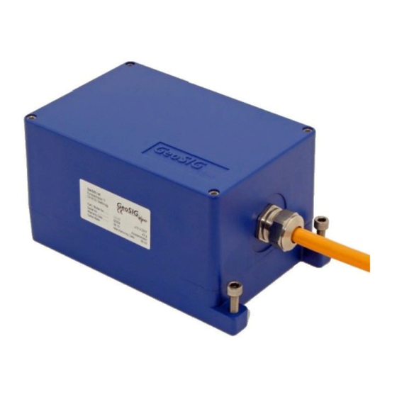
VE-1x/2x Series Velocity Sensor
Installation and Operation Manual
GeoSIG Ltd
Company:
Wiesenstrasse 39, 8952 Schlieren, Switzerland,
Tel: +41 44 810 21 50, Fax: +41 44 810 23 50, E-mail: info@geosig.com
Author:
Ralph Böniger
Checked:
Dr. Talhan Biro
Approved:
Johannes Grob
Distribution:
GeoSIG Ltd, Customer on request
Advertisement
Table of Contents

Related Manuals for GeoSIG VE-1 Series

Summary of Contents for GeoSIG VE-1 Series
- Page 1 VE-1x/2x Series Velocity Sensor Installation and Operation Manual GeoSIG Ltd Company: Wiesenstrasse 39, 8952 Schlieren, Switzerland, Tel: +41 44 810 21 50, Fax: +41 44 810 23 50, E-mail: info@geosig.com Author: Ralph Böniger Checked: Dr. Talhan Biro Approved: Johannes Grob...
- Page 2 Copyright Notice No part of this document may be reproduced without the prior written consent of GeoSIG Ltd. The software described in this document is furnished under license and may only be used or copied in accordance with the terms of such a license.
-
Page 3: Table Of Contents
GS_VE-1x_2x_Operation_Manual_V09.docx/14.09.2020 VE-1x/2x Series Velocity Sensor Page 3 / 10 Table of Contents INTRODUCTION ..........................4 INSTALLATION ..........................4 2.1............................4 NSTALLING 2.1.1. Verifying Installation ........................ 5 2.2......................... 5 LECTRICAL ONNECTION 2.2.1. Connector Pin Assignment ...................... 5 2.2.2. Connecting to a Recorder ......................7 2.2.3. -
Page 4: Introduction
GS_VE-1x_2x_Operation_Manual_V09.docx/14.09.2020 VE-1x/2x Series Velocity Sensor Page 4 / 10 1. Introduction The GeoSIG VE-1x/2x series velocity sensors consist of the following sensor types: Frequency response 1 Hz to 315 Hz: • VE-11 uniaxial • VE-12 biaxial • VE-13 triaxial Frequency response 4.5 Hz to 315 Hz: •... -
Page 5: Verifying Installation
Make sure that your sensor is oriented properly for your requirements. Please contact GeoSIG if you wish to change any axis direction / orientation. You might as well utilize your sensor by not fixing it to the foundation (in the case of horizontal foundations) but rather by placing it on the foundation, taking measurements and relocating for temporary or mobile measurements. - Page 6 GS_VE-1x_2x_Operation_Manual_V09.docx/14.09.2020 VE-1x/2x Series Velocity Sensor Page 6 / 10 Table 1. VE Internal PCB Pin Assignment 12 Pin Name 12 Lead Cable Colour Description Sens_X_HI white X-Signal high Sens_X_LO brown X-Signal low Sens_Y_HI green Y-Signal high Sens_Y_LO yellow Y-Signal low Sens_Z_HI grey Z-Signal high...
-
Page 7: Connecting To A Recorder
When cabling is ordered as part of the system, GeoSIG engineers review the installation plan and the cable specifications as well as environmental conditions to assist you in achieving a reliable and cost effective installation. Following the guidelines outlined below will help further ensure your success. -
Page 8: Operation And Configuration
The polarity of the signal can be changed basically by exchanging the connections to the geophone. Also this action has to be coordinated with GeoSIG and must be executed by a skilled electrician. 3.2. Scale Factor / Gain The standard scale factor is 100 mm/s. -
Page 9: Operation Confirmation
(see section 3.3. Self Test) to verify the integrity of the system and installation. In precision applications we recommend a calibration audit interval of 1 year. GeoSIG can execute a calibration check, which is executed by using an accelerometer with a hardware integrator as reference velocity sensor on a shaker. - Page 10 GS_VE-1x_2x_Operation_Manual_V09.docx/14.09.2020 VE-1x/2x Series Velocity Sensor Page 10 / 10 1 Hz 1 Hz 4.5 Hz 4.5 Hz Original Additional Gain Final Signal: Characteristic Improves the low frequency 1 Hz response of Geophone response between 1 - 4.5 Hz to 315 Hz 5 Voltage to current converter (Optional-GS-320CL) 0 –...
Need help?
Do you have a question about the VE-1 Series and is the answer not in the manual?
Questions and answers