
Related Manuals for Boss Audio Systems MR250.4


Summary of Contents for Boss Audio Systems MR250.4
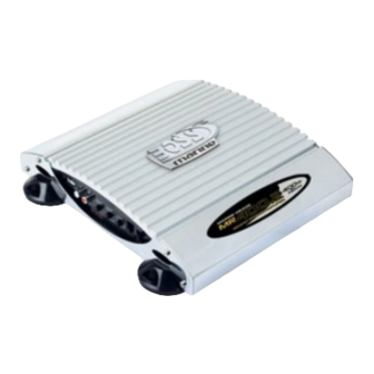
- Page 1 User's Manual CHANNEL BRIDGEABLE MOSFET MARINE POWER AMPLIFIER 4 CHANNEL BRIDGEABLE MOSFET MARINE POWER AMPLIFIER...
-
Page 2: Table Of Contents
MR400.2 Two Channel High Power MOSFET Marine Audio Amplifier Four Channel MR250.4 High Power MOSFET Marine Audio Amplifier Congratulations on your :lO~:S purchase of a Marine oWIlX'n~ Amplifier. It has been designed, engineered and manufactured to bring you the highest level of performance and quality, and will afford you years of listening pleasure. -
Page 3: Introduction
Introduction What is included? When first unpacking your new With the Marine MOSFET amplifier series, we are introducing amplifier, please check first that the package contains all of the items two new amplifiers, designed specifically for marine audio below. If something is missing, contact the store where you purchased the installations. -
Page 4: General Precautions
General precautions Protection Circuitry This amplifier incorporates special Before installing and l/sing YO(1r new protection circuitry Which will disable 3\)~ Marine amplifier, please be the amplifier if any of the following familiar with a'll the informa should occur: mal1ua/~ tion contained in this •... -
Page 5: Mounting The Amplifier
Mounting the amplifier Connecting the amplifier 1. Find a suitable location in the marine Before dOing <my wiring, look through vessel in which to mount the amplifier. this marual and identify the diagrams to follow for power. input and speaker Make sure there is sufficient air connections for your particular circulation around the intended... -
Page 6: Low Level Input Wiring
NOTE: Do not connect BOTH the high !evel and low level inputs from your receiver to your amplifier at the same time! 2-Channel Amplifier MR400.2 To Audio Outputs of head unit or signal processor 4-Channel Amplifiers MR250.4 REAR FRONT Audio Outputs 10l:=J of head unit or signal processor AmpRfier Manual· Ma"ne MOSFET... -
Page 7: Power And Speaker Wiring
Power and Speaker Wiring Channel Mode LEFT Speaker R.IGHT Speaker Bridged Mode SUBWOOFER Connecr the Negmive (-) SPEAKER terminal of speaker to /he IMPEDANCE R(-) amplifier terminal. 4-8 OHMS COnnec! the posJtlve (+) terminal of the spooker L(+) amplifier terminal. Marino MOSFET Amplifier Users Manual - page 10 2-Channel Amplifier Power and Speaker Wiring... -
Page 8: Channel Amplifier
4-8 OHMS Mmine MOSFET Amplifier User's Manual - page' 2 4-Channel Amplifier MR250.4 Power and Speaker Wiring Tri-mode operation allows you to connect this amplifier to a pair of main speakers plus a subwoofer on one pair of output channels. The main speakers will operate in STEREO while the subwoofer simultaneously operates in MONO. -
Page 9: Troubleshooting
Troubleshooting If you experience operation or perionnance problems with this product, compare your installation with the electrical wiring diagram on the previous pages. If problems persist, read the following troubleshooting tips which may help eliminate the problems. SYMPTOM POSSIBLE REMEDY Amplifier will not Check to make sure you have good ground connection.
Need help?
Do you have a question about the MR250.4 and is the answer not in the manual?
Questions and answers