
Related Manuals for Boltek LRX-1

Summary of Contents for Boltek LRX-1
- Page 1 BOLTEK CORPORATION Lightning Detection LRX-1 Lightning Network Detector ANT-50 Lightning Sensor / GPS Installation/Operation Guide LRX1ANT50-020819...
- Page 2 ANT-50 Lightning Sensor / GPS Disclaimer LRX-1 based lightning data is only approximate and should not be used for safety applications. Strike and storm locations indicated and alarm statuses may be erroneous and should not be used to safeguard personnel, equipment or data.
- Page 3 FCC Compliance Statement For United States Users This equipment is tested and found to comply with the limits for a Class B digital device, pursuant to Part 15 of the FCC Rules. These limits are designed to provide reasonable protection against harmful interference in a residential installation.
- Page 4 CAUTIONS LRX-1 based lightning data is only approximate and should not be used for safety applications. Strike and storm locations indicated and alarm statuses may be erroneous and should not be used to safeguard personnel, equipment or data. Install the ANT-50 Sensor on a calm clear day when no thunderstorms are expected.
-
Page 5: Table Of Contents
T able of Contents INTRODUCTION ......................1 HEORY OF PERATION ....................3 INSTALLATION ......................5 CONFIGURING THE LRX-1 ..................12 OPERATION ........................19 MAINTENANCE ......................21 TROUBLESHOOTING ....................23 SPECIFICATIONS ......................25... - Page 6 T able of Figures Figure 1: Lightning Detection Network Diagram ................. 3 Figure 2: LRX-1 / ANT-50 Connection Diagram ................. 6 Figure 3: Front View of LRX-1 ....................... 9 Figure 4: Default LRX Configuration File /home/lrx/LRX.ini ........13 Figure 5: Windows Device Manager ....................
-
Page 7: Introduction
Congratulations on your purchase of a Boltek LRX-1 Lightning Detection Network Detector. LRX-1 lightning data is only approximate and should not be used for safety applications. Strike and storm locations indicated and alarm statuses may be erroneous and should not be used to safeguard personnel, equipment or data. - Page 8 5: GPS Cable (CAT6) Adapter (N.A. or Int.) (CAT6) 9: 3 x Medium 7: 2 x Cable Grips 8: 3 x Large Mounting Mounting Clamps Clamps Unpack your LRX-1 and check to ensure all parts listed are included before installation.
-
Page 9: Theory Of Operation
C H A P T E R I N T R O D U C T I O N Theory of Operation … Figure 1: Lightning Detection Network Diagram... -
Page 11: Installation
(such as those just mentioned), and higher than the antenna. The LRX-1 receiver board has surge suppression in its input to protect against voltages induced into the antenna cable. It is also a good idea to purchase a surge suppressor to plug your computer into. -
Page 12: Figure 2: Lrx-1 / Ant-50 Connection Diagram
Keep the antenna and cable away from anything which might be struck by lightning. Lightning can jump from one object to another in its search for ground. Figure 2: LRX-1 / ANT-50 Connection Diagram... - Page 13 C H A P T E R I N S T A L L A T I O N Selecting Antenna Location...
- Page 14 Insert rubber into cable grip and tighten each nut until cables are no longer able to move. If the cables are not inserted into the correct connectors the LRX-1 will not function properly.
-
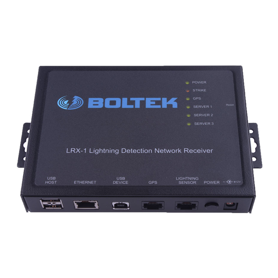
Page 15: Figure 3: Front View Of Lrx-1
Servers 4, 5 and 6 do not have status LEDs. Servers 1, 2 and 3 are control servers and have the ability to control and configure the LRX-1. Servers 4, 5 and 6 are data only servers and cannot control or configure the LRX-1. - Page 16 List. Once the LRX-1 has successfully connected to at least one control server the Server List can be updated remotely. The default entries in the Server List connect the LRX-1 to Boltek LDN servers. If you prefer we can remotely configure your LRX-1 to point at your servers, or configure the server list before shipment.
- Page 17 C H A P T E R C O N F I G U R I N G...
-
Page 18: Configuring The Lrx-1
Servers 1, 2 and 3 are Control Servers and have the ability to remotely configure the LRX-1. Servers 4,5 and 6 are Data Only Servers and do not have the ability to make any changes to the LRX-1 other than disconnecting their own connection, triggering an automatic reconnect. -
Page 19: Figure 4: Default Lrx Configuration File /Home/Lrx/Lrx.ini
C H A P T E R C O N F I G U R I N G Serial Number=10000 Trigger Level=250 [Server1] Enabled=1 Server=yourserver.com Port=9734 Password=yourpassword Mode=1 [Server2] Enabled=1 Server=yourserver2.com Port=9734 Password=yourpassword Mode=1 [Server3] Enabled=0 Server= Port=9734 Mode=1 Password= [Server4] Enabled=0 Server=... - Page 20 C O N F I G U R I N G Editing the LRX.ini file If your LRX-1 receiver was not pre-configured for you at the factory you will need to make a terminal connection to the LRX-1 and edit the configuration file yourself.
-
Page 21: Figure 5: Windows Device Manager
C H A P T E R C O N F I G U R I N G Figure 5: Windows Device Manager Use a terminal program such as PuTTY (free from www.putty.org) to connect to the higher number of the two COM ports. 115200 bps 8 data bits 1 stop bit... -
Page 22: Figure 6: Putty Configuration
C O N F I G U R I N G Figure 6: PuTTY Configuration Putty can also be used to make a SSH connection if desired once your LRX-1 is installed in a remote location (although you may need to configure the remote router or firewall). -
Page 23: Figure 8: Editing The Lrx.ini Configuration File Using Nano
Control-X to exit. Figure 8: Editing the LRX.ini Configuration File using nano Assigning an Ethernet IP Address The LRX-1 has DHCP enabled by default so it will automatically try to obtain an IP address if a DHCP server is available. - Page 24 If a DHCP server is not available on the local network it will be necessary to manually configure the IP address. First an available IP address needs to be assigned to the LRX-1 by the local network administrator. The network administrator will also provide the local netmask and gateway address.
-
Page 25: Operation
Server 2 and Server 3 only). Proper operation of the LRX-1 can be observed by a solid green server indication (Server 1, Server 2 and/or Server 3) and periodic flashing of the yellow Strike LED. A flashing green server LED indicates the LRX-1 is trying to connect to the server but is not connected. -
Page 27: Maintenance
M A I N T E N A N C E Maintenance The LRX-1 and ANT-50 will not normally require maintenance beyond a periodic inspection. During inspection verify that the ANT-50 mounts are secure and not corroded and that cables are not damaged or abraded. -
Page 29: Troubleshooting
Problem: The Strike light flashes once per second. The GPS light never comes on. Solution: The Lightning Sensor and GPS cables are swapped. Unplug them from the LRX-1 and swap the connections. Problem: The Server light(s) never stops flashing. No server lights are illuminated constant green. -
Page 31: Specifications
A P P E N D I X – S P E C I F I C A T I O N S Appendix Specifications LRX-1 LED Indicators Power (green) On when power is applied Strike (yellow) Flashes as strikes are detected... - Page 32 0 to 99% non-condensing Agency Approvals CE, FCC, cULus, C-tick Warranty 1 Year Ordering Information LRX1-KIT-120V-100FT LRX-1/ANT-50 kit for 120VAC LRX1-KIT-220V-100FT LRX-1/ANT-50 kit for 100-240VAC Standard kit includes 100’ / 30 m sensor cables. Additional cable lengths available on request.
- Page 33 A P P E N D I X – S P E C I F I C A T I O N S Kits include: • LRX-1 Lightning Network Detector • ANT-50 Lightning Sensor / GPS • Pole Mount Bracket / Mast for ANT-50 •...
Need help?
Do you have a question about the LRX-1 and is the answer not in the manual?
Questions and answers