
Summary of Contents for LTT 24
- Page 1 LTT 24 1 - 32 Channel Installation Guide & User Manual LTT Labortechnik Tasler GmbH Friedrich-Bergius-Ring 15 D-97076 Würzburg...
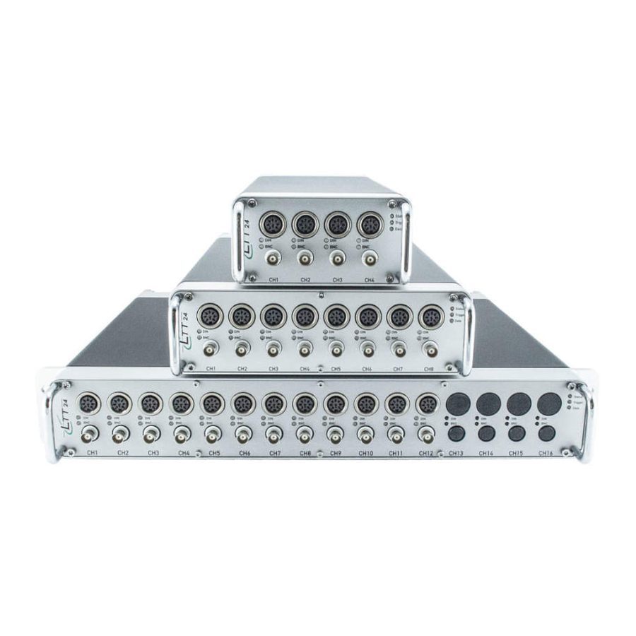
- Page 3 LTT Labortechnik Tasler GmbH The multi-functional data acquisition device LTT24 combines the functionality of a Transient-Recorder with 24 bit ADC and 4 MSample/s per channel with amplification functions for voltage, current, IEPE (ICP®), strain gauge, resistance, temperature, charge and more.
- Page 4 LTT24 Manual © 2015 LTT Labortechnik Tasler GmbH All rights reserved. No parts of this work may be reproduced in any form or by any means - graphic, electronic, or mechanical, including photocopying, recording, taping, or information storage and retrieval systems - without the written permission of the publisher.
-
Page 5: Table Of Contents
Signal Conditioning ................................27 Operation Conditions ................................28 2 DIN socket pin assignment ........................... 29 3 Binder Series 693 power plug ........................... 30 Part V Troubleshooting 1 Problems with computer connection ........................... 32 Index © 2015 LTT Labortechnik Tasler GmbH... -
Page 7: Part I Installation
Installation Part... -
Page 8: Unpacking
If your LTT24 device or parts of the accessory seem to be damaged or incomplete, please contact LTT immediately. Do not disassemble the device or the delivered power supply on your own! When using your own power supply, refer to chapter Specifications for notes on power requirements. -
Page 9: Setup And Connections
8110 (TCP), 8111 (UDP) and 8112 (UDP). If the LTT24 is not recognized by your computer, please refer to chapter Troubleshooting to get further information and assistance. © 2015 LTT Labortechnik Tasler GmbH... -
Page 10: Software
LTTpro on that operating system. If you want to run LTTpro on Linux, please contact LTT software development for binaries and instructions. If you want to implement LTT24 device(s) in your own measurement or analysis product you can use ltt2api libraries for complete control and data handling on our devices. - Page 11 Operation Part...
-
Page 12: Part Ii Operation
RAM buffer - not all data will be recorded or transferred to your computer. If Status LED turns red, a severe error condition has reached. Turn off device immediately and check for proper environment conditions. © 2015 LTT Labortechnik Tasler GmbH... -
Page 13: Overview
ChnGround is same as PIN 2 of the DIN socket, only one interface (DIN or BNC) is available at a time. Caution: Channels that come with Pulse Recognition or DACout option have ChnGround and Pin 2 shortened all the time! © 2015 LTT Labortechnik Tasler GmbH... -
Page 14: Couplings (Sensor Types)
STRAIN GAUGE: Fullbridge You will see activity of DIN socket or BNC jack at the channel LEDs. Green LED signals channel activity, orange LED signals active supply. DIN IN a ctive BNC IN a ctive © 2015 LTT Labortechnik Tasler GmbH... -
Page 15: Single Ended (Se) Operation
Make sure that attached source is able to drive low-impedance devices. Caution: In CURRENT operation (AC and DC), currents above ±200 mA will heat up the 5.1 shunt resistor and will eventually damage the amplifier! © 2015 LTT Labortechnik Tasler GmbH... -
Page 16: Differential Ended (De) Operation
Differential Ended (DE) Operation Differential Ended (DE) measurement with DIN socket: VOLT (DE) CHARGE (DE) DE pin a ssignm e nt Note: With DUAL-BNC option VOLT (DE) and CHARGE (DE) mode is also available on Dual-BNC jack. © 2015 LTT Labortechnik Tasler GmbH... -
Page 17: Iepe (Icp™)
2-wire: Constant Current (CC) is internally bridged to IN+, IN- is bridged to ChnGround (GND) 3-wire: IN- is bridged to ChnGround (GND), Constant Current has to be connected 4-wire: ChnGround and Constant Current have to be connected in addition to IN+ and IN- © 2015 LTT Labortechnik Tasler GmbH... -
Page 18: Strain Gauge: Quarterbridge
Qua rte rbridge pin a ssigm e nt Note: Quarterbridge always uses Sense+ line! In 2-wire operation, connect Sense+ with P+ as close as possible to the strain gauge. Caution: No further resistors are allowed with Quarterbridge coupling! © 2015 LTT Labortechnik Tasler GmbH... -
Page 19: Strain Gauge: Halfbridge
Note: You should avoid to use coax cable for P+ and P- because cable cross-section of coax cable for shield is different to those of center. Sensors with 5 wires (including Sense-): Keep the Sense- unattached. Caution: be aware of the antenna effect on open wires! © 2015 LTT Labortechnik Tasler GmbH... -
Page 20: Strain Gauge: Fullbridge
You should avoid to use coax cable for P+ and P- because cable cross-section of coax cable for shield is different to those of center. Sensors with 6 wires (including Sense-): Keep the Sense- unattached. Caution: be aware of the antenna effect on open wires! © 2015 LTT Labortechnik Tasler GmbH... - Page 21 Optional Features Part...
-
Page 22: Part Iii Optional Features
The high speed flash memory of these SSDs is fast enough to handle the maximum LTT24 data rate of 256 MB/s (that is when 16 channels are turned on at maximum sample rate of 4 © 2015 LTT Labortechnik Tasler GmbH... -
Page 23: Accumulator
The accumulators in your LTT24 are lithium polymer (LiPo) based and not intended for replacement. Charge of LTT24 internal accumulators is done automatically with delivered power supply. Caution: Never open the device in order to change or upgrade the internal accumulators of the LTT24! © 2015 LTT Labortechnik Tasler GmbH... - Page 25 Specifications Part...
-
Page 26: Part Iv Specifications
± 250mV, 5V, 50V (optional ± 200V) Input dividers (1:10), (optional 1:100) Coupling Single-Ended (AC/DC), Differential (AC/DC) Dynamic range 118dB @ 5kHz Sample/s (gain 1) 109dB @ 125kHz Sample/s (gain 1) 94dB @ 4MHz Sample/s (gain 1) © 2015 LTT Labortechnik Tasler GmbH... -
Page 27: Output Characteristics
1mV/pC, 11mV/pC Range: ± 5nC, ± 100pC High-pass: 0.15Hz; 1.5Hz; 15Hz Auto charge Clear; manual Clear TEDS (optional) Puls input Signal input +/-30V Time resolution 1ns (1GHz) Direction detection Zero marker Digital inputs (optional) © 2015 LTT Labortechnik Tasler GmbH... -
Page 28: Operation Conditions
12-16VDC (absolute max. rating 10 - 35VDC) 100 - 240VAC with external power supply Environmental Temperature +10°C to +40°C Extended temp. range 0°C to +50°C on request Operation System Windows XP / Vista / 7 / Linux and others © 2015 LTT Labortechnik Tasler GmbH... -
Page 29: Din Socket Pin Assignment
Note: Pin assignment may vary with different options. For example, pulse recognition feature excludes TEDS, and, depending on further options, also Sense+ and Constant Current. With a pre-configured DIN cable (LTT order no. 91-24-025), use the following color assignment: Color... -
Page 30: Binder Series 693 Power Plug
When using your own power supply for LTT24 devices, use a Binder series 693 plug with the following pin assignment. Numbers are plotted from rear as looking to an open plug from behind: Note: Due to power supply compatibility to former LTT devices, the center pin of the Binder plug... -
Page 31: Part V Troubleshooting
Troubleshooting Part... -
Page 32: Problems With Computer Connection
A software (" LTTFWUpdate") is supplied for changing the network settings of the delivered external computer system. Ask your network administrator for assistance if you have problems with the network setup. © 2015 LTT Labortechnik Tasler GmbH... - Page 33 Use USB 3.0 interface for higher data-rates if available. When using the LTTROAD-service, the data rate will not exceed ~80% of the possible speed when working in direct mode. Use "Physical Disk" operation mode in LTTpro software if possible. © 2015 LTT Labortechnik Tasler GmbH...
-
Page 35: Index
- L - Data data-blocks device emulation mode LEDs 12, 13 Differential Ended Linux 10, 32 Digital inputs LiPo DIN socket 12, 13, 15, 29 low-impedance Direction detection ltt2api display-size LTTpro 10, 22, 32 DUAL-BNC © 2015 LTT Labortechnik Tasler GmbH... - Page 36 - R - white-list WinMagic™ SecureDoc® range limits recording - Z - Recording media Release Report replay Zero marker resistor Run as administrator - S - safety precautions Schuko® plug security rules Sense 27, 29 © 2015 LTT Labortechnik Tasler GmbH...
Need help?
Do you have a question about the 24 and is the answer not in the manual?
Questions and answers