Table of Contents
Advertisement
Quick Links
Advertisement
Table of Contents

Related Manuals for Norsonic nor1216

Summary of Contents for Norsonic nor1216
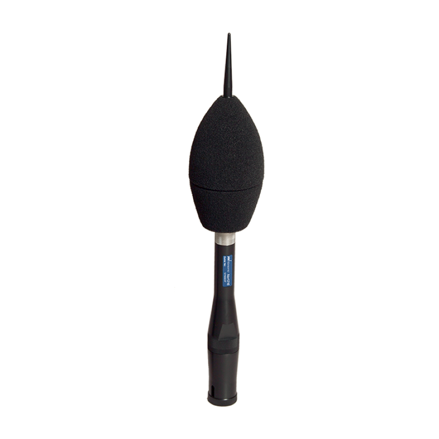
- Page 1 INSTRUCTION MANUAL Outdoor microphone nor1216...
- Page 3 Outdoor microphone nor1216...
- Page 4 Norsonic AS reserves the right to amend any of the informa- tion given in this manual in order to take account of new developments.
-
Page 5: Table Of Contents
Directional response ........................12 Frequency response ........................13 Self-noise and wind ........................14 Chapter 4 Connecting the Nor1216 to Sound Analyser Nor140 and Sound & Vibration Analyser Nor150 ..............15 Connecting to Nor140 ......................16 Connecting to Nor150 ......................17 Chapter 5... - Page 6 Content Chapter 6 Specifications .....................19 Mounting direction ........................19 Acoustic performance ........................19 General ............................ 19 Frequency response ......................19 Directional response ......................19 General ............................19 Conformity ............................. 20 Protection provided by the enclose ................... 20 Accessories and spare parts ...................... 20...
- Page 7 Outdoor microphone nor1216...
-
Page 9: Chapter 1 Introduction
The microphone contains elements for protecting the The base of the Nor1216 is made of an electrical insulat- microphone cartridge from rain and snow, dust and ing material. The microphone body will be fully insulated insects, satisfying IP 55 requirements. -
Page 10: Chapter 2 Assembling
Assembling Birdspike Wind, dust and water protection The outdoor microphone Nor1216 is shipped fully as- sembled. However, in order to mount the microphone cable the unit has to be opened. Upper part Depending on the application, you will need a mast... -
Page 11: Mounting On A Mast
For permanent installations we recommend to mount protection. the Nor1216 on a pole rather than using the 3/8” cam- We recommend making the combined grounding era tripod treads. Remove the optional tripod adapter... -
Page 12: Chapter 2 Microphone Calibration
Chapter 3 Microphone calibration Microphone calibration The Nor1216 can be calibrated with a sound calibra- tor for ½” microphones without the need for special couplers. We recommend using Nor1251 (1000 Hz) or Nor1253 (250 Hz). Unscrew the upper part of the microphone to gain access to the microphone cartridge. -
Page 13: Chapter 3 Technical Description
Instruction Manual Technical description Birdspike Upper part Windscreen The outdoor microphone Nor1216 is based on a ½” working standard microphone type WS2F according Microphone cartridge to IEC 61094-4. Two types of microphones are offered; - Nor1225, a free field microphone requiring 200V Rain hood polarisation voltage. -
Page 14: Electrical Description
Electrical description When Nor1216 substitute a normal measurement The power to the Nor1216 will normally be supplied microphone on a sound level meter, a correction of the from a Norsonic sound analyser Nor140 or Nor150 frequency response is normally needed to retain the... - Page 15 10 volt corresponding heater resistor which is used in Nor1216 to 140 dB peak sound pressure level for the Nor1227 / to rise the temperature of the microphone and Nor1225 microphone cartridge (50mV/Pa).
-
Page 16: System Check
Chapter 4 Technical description System check A typical level for the returned signal is 45 mV with an excitation of 1 volt corresponding to a sound level of The system check terminal, pin 1, shall be terminated 92 – 95 dB dependant of the microphone cartridge ca- to signal ground or the signal output when the micro- pacistance. -
Page 17: Frequency Response
Norsonic Nor1216 Instruction Manual Frequency response The typical frequency response for the preamp- lifier is shown below. The frequency response for the outdoor microphone system is therefore mainly deter- mined by the microphone cartridge and the acoustic performance of the enclosure. -
Page 18: Self-Noise
Chapter 4 Technical description Self-noise The electrical noise when the microphone is substitut- ed by an 20 pF capacitor is shown on the graph above. 0 dB corresponds to 1 µV. For a microphone with a sensitivity of 50 mV/Pa (Nominal value of Nor1227 or Nor1225), 0 dB voltage also corresponds to the normal reference pressure for sound: 20 µPa and the noise level may be compared with sound pressure level di-... -
Page 19: Cables And Cable Length
Norsonic Nor1216 Instruction Manual Cables and cable length The Nor1216 with its preamplifier Nor1209A has excel- long cables. However, when the signal contains the lent driving capability for long cables. The signal out- combination of high amplitude and high frequency, put from the microphone preamplifier will be loaded by the capacitive loading will lead to high output current. -
Page 20: Directional Response
The upper adjacent figure shows the directional re- sponse for Nor1216, when the reference axis is verti- cal, for the frequencies 1000 Hz, 4000 Hz and 8000 IEC 61672-1 specifies tolerance limits for any fre- quency. -
Page 21: Frequency Response
Nor140 (for program in the recommended vertical direction. The response version 2.0 and above), just select Nor1214/Nor1216 marked “Horizontal” is the response for sound ap- in the input setup menu. When used with Nor118 (and... -
Page 22: Self-Noise And Wind
Chapter 4 Technical description Self-noise and wind The figure below shows typical self-noise for the mi- crophone system as levels for the various 1/3-octave frequency bands re. 20 µPa when the microphone is placed in a horizontal, laminar flow of air with speed 0, 5 and 10 m/s, respectively. -
Page 23: Connecting The Nor1216 To Sound Analyser Nor140 And Sound & Vibration Analyser Nor150
Nor1216 to Sound Analyser Nor140 and Sound & Vibration Analyser Nor150 The Nor1216 is designed to be used with the Sound Analyser Nor140 and Sound & Vibration Analyser NOTE: Nor140 with serial number below Nor150. These analysers support all the needed cor-... -
Page 24: Connecting To Nor140
In the SETUP – 1 (Instrument menu) – 4 (Input menu), you select which type transducer you have connected. Select either “1214/16 Ver” for Nor1216 with vertical frequency correction applied and “1214/16 Hor” for Nor1216 with horizontal frequency correction applied. -
Page 25: Connecting To Nor150
When the verification date is due, the instrument will display a warning at start up. Name; Use Nor1216 as a part of the name to easily identify it later. Type; Select outdoor microphone. Make sure pre-... -
Page 26: Chapter 5 Maintenance
Chapter 6 Maintenance Maintenance The need for maintenance depends largely on the environmental conditions where the microphone sys- tem is used. Contamination of dust, ice or snow on the windscreen may alter the acoustic performance. For most applications, it will be sufficient to check the microphone periodically by using the system check facility, e.g. - Page 27 Norsonic Nor1216 Instruction Manual Specifications Mounting direction Directional response The microphone shall be mounted with the tip pointing The directional response satisfies the requirements for upwards and the axis of symmetry shall be vertical. a Class 1 sound level meter according to IEC61672-1.
- Page 28 The microphone satisfy the requirements for a Class 1 sound level meter according to IEC 61672-1 when Windshield upper part: Norsonic part no. Nor4529 combined with Nor140 with sofware version 2 and above or Nor150 equipped with software version 1.2 Assembled upper part with windscreen: and upwards.
- Page 29 Norsonic Nor1216 Instruction Manual...
- Page 31 All our products are tested individually before they leave the factory. This Declaration of Conformity does not affect our warranty obligations. Dagfinn Jahr Tranby, February 2014 Quality Manager The declaration of conformity is given according to EN 45014 and ISO/IEC Guide 22. Norsonic AS, P.O. Box 24, N-3421 Lierskogen, Norway...
- Page 32 P.O. Box 24 N-3421 Lierskogen Norway Norsonic AS supplies a complete range of instrumentation for acoustics – from sound calibrators, micro- Tel: +47 3285 8900 phones and preamplifiers; via small handheld sound level meters to advanced, yet portable, real time...
Need help?
Do you have a question about the nor1216 and is the answer not in the manual?
Questions and answers