Advertisement
Quick Links
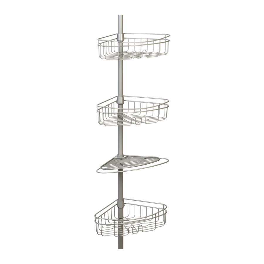
Assembly Instructions
Model
2176NNWM (Satin Nickel)
2176HBWM (Oil Rubbed Bronze)
For Spanish and French instructions, start on page 11.
Para instrucciones en español y francés, comience en la página 11.
Pour les instructions espagnoles et françaises, commencez à la page 11.
SAFETY WARNING:
Make sure you are installing in a clean, dry and safe
environment. DO NOT STAND ON TUB LEDGE.
Before You Begin:
Thank you for purchasing this product. Please identify
all parts and hardware pieces before you begin.
When laying out parts, place them on a soft surface
to prevent scratching.
If any pieces are missing, call our Toll Free Number
1-800-892-3986 between 8:00AM-5:00PM EST Monday
through Friday.
MCS 11/04/2019
Pg 1 of 20
PLEASE DON'T RETURN TO STORE CALL US FIRST
(800) 892-3986
customerservice@zenith-products.com
1-800-892-3986
IS02176-I
Advertisement

Summary of Contents for Mainstays 2176NNWM
- Page 1 Assembly Instructions Model 2176NNWM (Satin Nickel) 2176HBWM (Oil Rubbed Bronze) For Spanish and French instructions, start on page 11. Para instrucciones en español y francés, comience en la página 11. Pour les instructions espagnoles et françaises, commencez à la page 11.
-
Page 2: Tools Needed
Tools Needed: List of Parts: A 3/4 in. tube x1 F Spacer x3 G Small end cap x1 B Straight tube x1 (spring packed inside) H Large end cap x1 Soap Tray x1 C Long tapered tube x1 J Shelf x3 K Wedge x4 D Medium tapered tube x1 L Transition ring x1... - Page 3 STEP 1 1. Measure the distance between the tub ledge or the shower stall floor to the ceiling to the nearest half inch. fig.1 tub ledge (opening height) fig. 2 shower stall floor (opening height) 1-800-892-3986 IS02176-I Pg 3 of 20...
- Page 4 STEP 2 1. See the chart to determine what tubes (C), (D), (E) and spacers (F) are needed. NOTE: No matter the distance, tubes (A) and (B) are ALWAYS used. Use Tubes (C), (D), and (E) Number of Spacers (F) Opening Height (see fig.1, 2) as Needed Used...
- Page 5 STEP 3 NOTE: ASSEMBLY SHOWN FOR 97 IN. OPENING HEIGHT. The following assembly should be modified based on your opening height, SEE CHART ON PAGE 4. 1. Place a wedge (K) (tapered or rounded end up) on a long tapered tube (C) approximately half way down.
- Page 6 STEP 4 1. Place the tapered end of the long tube (C) into the untapered end of the medium tube (D), as shown. tapered end at the top tapered end at the top 1-800-892-3986 IS02176-I Pg 6 of 20...
- Page 7 STEP 5 1. Place the large end cap (H) onto the short tapered tube (E). 2. Place the tapered end of the short tapered tube (E) into the untapered end of the bottom tube assembly, as shown. bottom tube assembly tapered end at the top 1-800-892-3986 IS02176-I...
- Page 8 STEP 6 NOTE: ASSEMBLY SHOWN FOR 97 IN. OPENING HEIGHT. The following assembly should be modified based on your opening height, SEE CHART ON PAGE 4. 1. Place straight tube (B) on top of the assembly. 2. Insert three spacers (F) into the straight tube (B), as shown. spring is packed inside straight tube (B) 1-800-892-3986...
- Page 9 STEP 7 1. Place the small end cap (G) onto the 3/4 in. tube (A). 2. Insert the transition ring (L) into the straight tube (B). 3. Slide the 3/4 in. tube (A) through the transition ring (L) and into the straight tube (B), as shown. 4.
- Page 10 STEP 8 NOTE: Make sure you are installing in a clean, dry and safe environment. 1. Compress top of the unit against the ceiling in the desired location. 2. Move the bottom end into place so that the unit is in a vertical position. fig.1 tub ledge (opening height) fig.
-
Page 11: Advertencia De Seguridad
Instrucciones de Ensamblado / Instructions de montage Modelo / Modèle 2176NNWM (Niquél Satinado / Nickel satiné) 2176HBWM (Bronce tratado con aceite / Bronze huilé) Consultas sobre productos - Instalación Ayuda Questions sur le produit - Aide à l’installation ¡Nuestros especialistas en productos están aquí para ayudar! Nos spécialistes de produit sont là... - Page 12 Herramientas Necesarias: Outils nécessaires : Lista de Piezas: Liste des pièces : Espaciador x3 Tubo de 3/4 de pulg x1 entretoise x 3 tube de 19 mm (3/4 po) x 1 G Cubierta terminal pequeña x1 petit embout x 1 B Tubo recto x1 H Cubierta terminal grande x1 (con resorte embutido...
- Page 13 STEP 1 1. Mida la distancia entre el reborde de la bañera o 1. Mesurez la distance entre le rebord de la baignoire el piso del cubículo de la ducha hasta el cielorraso ou le plancher de la cabine de douche et le plafond, redondeando a la media pulgada más cercana.
- Page 14 STEP 2 1. Vea la tabla para determinar cuáles tubos (C), (D), (E) y 1. Reportez-vous au tableau pour déterminer quels espaciadores (F) son necesarios. tubes (C), (D), (E) et entretoises (F) sont nécessaires. NOTA: Cualquiera sea la distancia, SIEMPRE se usan REMARQUE : quelle que soit la distance, les tubes (A) et (B) los tubos (A) y (B).
- Page 15 STEP 3 NOTA: ENSAMBLE MOSTRADO PARA INSTALACIÓN EN REMARQUE : ASSEMBLAGE ILLUSTRÉ POUR L’OUVERTURE ALTURA DE APERTURA DE 97 PULGADAS. El siguiente DE 246.5 CM (97 PO) DE HAUT. L’assemblage suivant ensamble se debe modificar basándose en la altura doit être modifié en fonction de la hauteur de de apertura, VER TABLA EN LA PÁGINA 14.
- Page 16 STEP 4 1. Coloque el extremo ahusado del tubo largo (C) 1. Enfilez l’extrémité conique du tube long (C) dentro del extremo no ahusado del tubo mediano (D), dans l’extrémité non conique du tube moyen (D), como se ilustra. comme illustré. extremo con ahusamiento en la parte superior extrémité...
- Page 17 STEP 5 1. Coloque la cubierta terminal grande (H) sobre el 1. Enfilez le gros embout (H) au bout du tube conique tubo corto ahusado (E). court (E). 2. Coloque el extremo ahusado del tubo corto ahu- 2. Enfilez l’extrémité conique du tube conique court (E) sado (E) dentro del extremo que no está...
- Page 18 STEP 6 NOTA: ENSAMBLE MOSTRADO PARA INSTALACIÓN DE REMARQUE : ASSEMBLAGE ILLUSTRÉ POUR L’OUVERTURE APERTURA DE 97 PULG. DE 246,5 CM (97 PO). 1. El siguiente ensamble se debe modificar basándose 1. L’assemblage suivant doit être modifié en fonction en la altura de apertura, VER TABLA EN LA PÁGINA 14. de la hauteur de l’ouverture.
- Page 19 STEP 7 1. Coloque la cubierta terminal pequeña (G) sobre el 1. Placez le petit embout (G) sur le tube de tubo de 3/4 pulg. (A). 19 mm (3/4 po) (A). 2. Inserte el aro de transición (L) dentro del tubo 2.
- Page 20 STEP 8 NOTA: Asegúrese de que está haciendo una instalación REMARQUE : assurez-vous d’installer le produit dans en un entorno limpio, seco y seguro. un endroit propre, sec et sécurisé. 1. Comprima la parte superior de la unidad contra el 1.
Need help?
Do you have a question about the 2176NNWM and is the answer not in the manual?
Questions and answers