
Subscribe to Our Youtube Channel
Related Manuals for FW Murphy Centurion C5 M-VIEW MV-5-C

Summary of Contents for FW Murphy Centurion C5 M-VIEW MV-5-C
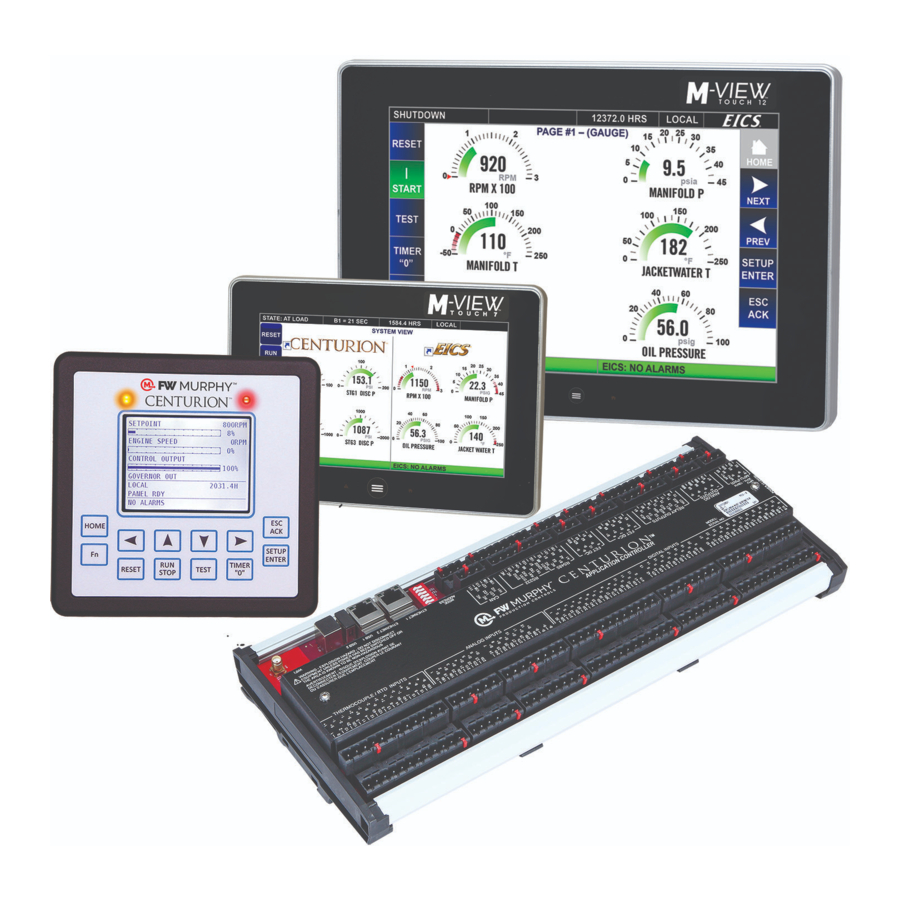
- Page 1 ™ Centurion ™ M-VIEW Monochrome LCD (MV-5-C) Operations Manual 00-02-1031 2019-08-07 Section 50...
- Page 2 Body. Observe all Warnings and Cautions at each section in these instructions. Device shall be wired in accordance with NEC, CEC or other local code, as applicable. Please contact FW Murphy immediately if you have any questions.
- Page 3 For Class I, Division 2: This equipment is an open-type device and is meant to be installed in an enclosure suitable for the environment such that the equipment is only accessible with the use of a tool. This equipment is suitable for use in Class I, Division 2, Groups A, B, C and D or non- hazardous locations only.
- Page 4 THIS PAGE INTENTIONALLY LEFT BLANK...
-
Page 5: Table Of Contents
Operational Screens ..............................14 User-Configurable Screens ........................14 Map of Operational Screens ........................14 FW Murphy Logo Screen ........................14 Corporate and Configuration Information Screen ................... 15 Bootloader and Firmware Information Screen ..................15 Digital Input Status Screen ........................15 Temp Input Status Screen ........................ - Page 6 State Timer Setup Screen ........................23 Maintenance Timer Setup Screen ......................23 Control Loop Setup Screen ........................24 Miscellaneous Setup Screen ........................27 Digital Input Setup Screen ........................28 Pulse Input Status Screen ........................28 Digital Output Setup Screen ........................29 Analog Inputs Setup Screen ........................
-
Page 7: Introduction
Interface) or with no operator interface at all, it is optimally configured and field-configurable using the Centurion Configuration Tool, powerful software developed to configure the controller. Parameters can be modified in the field without special need for laptop or software by utilizing FW Murphy’s specially programmed M-VIEW controller display. - Page 8 MV-5-C Display – Back Side The LEDs are located next to the serial port connections. All Ports RX/TX LEDs include: The serial activity LEDs blink with every transmitted or received message. The RX LED blinks Red when a packet is received by the display. The TX LED blinks Green when a packet is transmitted by the display.
- Page 9 C5-1 Digital Input LED Indicators – Digital Inputs Green LED: On - Input active (DC+ or -) Off - Input active (open) C5-1 Digital Output LED Indicators – Relay Outputs, FET DC+, FET DC- Green LED: On - Output on Off - Output off C5-1 Communication LED Indicators - RS232, RS485, CAN bus RED LED:...
-
Page 10: Mv-5-C Display Features
Display Features The display module is a highly integrated operator interface specially programmed to complement and support the Centurion controller. The primary purpose of the display is to: view controller operational information view/edit controller operational parameters send commands to controller, such as stop, edit and reset Home Screen / Landing Page Your default Home Screen / Landing Page is determined by the first page configured in the Centurion configuration, and may look similar to this example. -
Page 11: Navigation Keys
Navigation Keys The keys actions are relative to the location of the cursor and the screen being displayed. The following table describes the keys and their function for each screen type: Operating Status screens Setup screens (password required) ... - Page 12 Description Operating Status Screen - Scroll up one line. Automatically repeats if held down continuously until reaching the first line. For history screens, scrolls up one history (for example: shutdown or event). Set Up Screen - Scroll up one line. Automatically repeats if held down continuously until ARROW reaching the first line.
-
Page 13: Reading The Screen
Reading the Screen The actual number of Operating Status screens is set by the controller configuration. Operating Status screens of the Line-by-Line type have seven (7) lines visible at a time. Setup screens have five (5) lines visible at a time. Seeing the Up and Down Arrows on the screen indicate that more lines are available on the page. -
Page 14: Maneuvering In Edit Mode
Maneuvering in Edit Mode In the edit mode you may see the curser blinking where it’s being edited. In some instances, a word rather than a value is represented and you may choose one or the other, such as Yes or No, On or Off in the Edit Mode. ... -
Page 15: Status And Mode Of The Controller
Status and Mode of the Controller Local and Remote are the two Operating Modes of the controller. The operation may differ depending on what Mode the controller is currently displaying. The Mode can be changed by pressing certain keys, if the configuration allows for Remote mode. ... -
Page 16: Password
Password Passwords and Screen Access Some settings are password protected, including the setup screens. There are two separate levels of passwords to accommodate several security needs: Standard password – Allows access to some features except the super user menu and setup editing. Super User password –... -
Page 17: Before Starting The Equipment For The First Time
From the Centurion Home Screen / Landing Page, touch the Arrow key to scroll left until you find the screen FW Murphy – MVIEW screen. c. Verify that the configuration description matches the one you previously recorded from the drawing legend. - Page 18 4. Press the Setup Enter key to open the Password screen. a. Use the Arrow keys to enter your password. Default passwords are Operator 164, Super User 133. If further details are needed, see Display Passwords. 5. Once the password is entered, the display opens the Setpoints Setup screen. Use the right and left Arrow keys to find the screen you want to view / edit.
- Page 19 7. Start the unit. a. Clear any Alarms Class A (always armed) faults from the system. On the display, the Unit State will read Panel Ready if no Class A shutdown condition exist. b. Press and hold the Run Stop key on the display for 2 seconds. This will initiate the start cycle. Depending on your configuration, the Centurion will send signals to possibly prelube the equipment, check pre-starting permissives, and then signal the driver to start the equipment.
-
Page 20: Operational Screens
Based on configuration, up to 9 custom screens here. FW Murphy Logo Screen The FW Murphy logo is the first screen in the sequence of display screens and can be viewed by holding down the left arrow until scrolling left ceases. -
Page 21: Corporate And Configuration Information Screen
Bootloader and Firmware Information Screen The Bootloader and Firmware Information screen provides information for you to give our FW Murphy Technical Support staff should you need to call them. Such as, the bootloader and firmware versions for the core module, the MView display and the expansion module (if used). -
Page 22: Temp Input Status Screen
Temp Input Status Screen The user can see the state of each temperature input in a table—whether it is OK or has a wiring fault. X = OK p = Wire Fault Leaking to DC+ (input still able to be read, but some error is being introduced) n = Wire Fault Leaking to DC- (input still able to be read, but some error is being introduced) -
Page 23: Event History Screen
Event History Screen The history of the last 32 events is displayed on this screen, with the most recent at the top of the list and the oldest at the bottom. The number displayed in the top right corner indicates how many entries are in the list. -
Page 24: Gage Display Screen
Gage Display Screen This is an example of a custom gage display. This display provides larger characters for easier viewing as well as a means to prominently display items of interest. Line-by-Line Screen This is an example of a custom line-by-line status screen. If the parameters do not fit in the viewable area of the screen, up/down arrow icons will appear at the bottom of the screen to indicate the ability to scroll up or down to see... -
Page 25: Rod Load Screen
Rod Load Screen If Rod Load calculations have been enabled on the Centurion Configuration, the last page to the right will contain the Compressor Rod Load information. The calculated tension and compression forces on the rod are displayed in Imperial or Metric units as configured by the user. -
Page 26: Setup Screens And Menus
Setup Screens and Menus After entering your password, use the right and left arrow to view the Setup Screens available at your security level. The setup screens provide access to system parameters. These settings can be modified with appropriate password access. The two bottom lines in the setup screens list navigation and command options that are available with the selected item. -
Page 27: Setpoints Setup Screen
Setpoints Setup Screen Up to 192 setpoints may be configured in the system by the Centurion Configuration Tool software. The values for the setpoints are user editable. Setpoints are data entries used in greater than or less than comparisons of signals based on variable input types such as MPU, analog or thermocouples. -
Page 28: General Timer Setup Screen
General Timer Setup Screen User may edit all general purpose timers. Generally, global timers affect driver operation. They also help define an event arming condition. B1: All event types can be associated with, and locked out by, a Bx timer. B1 is the first global timer used for delaying an event condition detection. -
Page 29: State Timer Setup Screen
State Timer Setup Screen User may edit all state timers if marked in use. State 1 – Panel Ready and 23 – Shutdown are Read Only and cannot be edited. The states used for a given application are configured by the Centurion Configuration Tool software. -
Page 30: Control Loop Setup Screen
Control Loop Setup Screen Users may view and edit up to eight (8) configured control loops. The settings on this page will differ depending on the type of control configured for the system. The control loops all operate on the principle of a 0-100% calculated output with special considerations for the Digital loop types. - Page 31 7. Max Rate of Decrease/Increase: This is a maximum slew rate setting for the output change per loop update time. 8. Set Output % (Manual) *: This is the control output value data entry for manual mode. 9. Override 1-3 Ramp time*: Set the interval used to modify the calculated output when a configured override signal is active.
- Page 32 Control Loop Setup Screen (continued) a) Analog/Digital PID loop specific setpoints: 1. Proportional: Proportional gain tuning for the control process. 2. Integral: Integral time constant (%/sec) tuning for the control process. Integration adjusts the output value on the accumulated of the error over time. 3.
-
Page 33: Miscellaneous Setup Screen
Miscellaneous Setup Screen a) Core/Expansion Flywheel Teeth: Engine: Define a value for flywheel teeth (Pulses Per Revolution) used to calculate RPM. Motor: When setpoint set to zero, crank attempts becomes # of starts per hour (Short cycle limit) for electric motor applications. -
Page 34: Digital Input Setup Screen
Digital Input Setup Screen For all configured digital inputs, the user may edit: a) Signal Type - Select one of three choices; normally open, normally closed DC+ or normally closed DC-. b) Signal Filter - Select None to disable filter function for the digital input. -
Page 35: Digital Output Setup Screen
Digital Output Setup Screen Digital output: For all configured digital outputs, the user may edit: a) Action - Select normally open or normally closed. Normally closed inverts the logic associated with the output if desired. b) Raw Status: The actual output state. To force the output, toggling the normally open to normally closed will cause it to invert state. -
Page 36: Analog Inputs Setup Screen
Analog Inputs Setup Screen For all configured analog input devices, the user may edit: a) Scaled Minimum - Minimum engineering scale for the input when the raw counts are at the raw count offset reading. Example: 0 PSI for a 0-100 PSI transmitter. b) Scaled Maximum - Maximum engineering scale for the input when the raw counts are at the raw count offset + raw count max (total raw counts). -
Page 37: Analog Outputs Setup Screen
Analog Outputs Setup Screen Centurion analog output hardware is ranged to 4-20mA. The actual analog output % will be shown for each channel. For all configured analog output devices, the user may edit: a) Minimum - Minimum % output. In most cases, 0% addresses a typical application (4mA). -
Page 38: Temperature Inputs Setup Screen
Temperature Inputs Setup Screen The actual temperature reading in degrees will be shown per channel. For all configured temperature devices, the user may edit: a) Temperature: The actual measured sensor reading. b) Status: Real-time display of any wire faults that may exist for the sensor. -
Page 39: Rod Load Setup Screen
Rod load Setup Screen Rod Load setup screen is visible if Compressor Rod Load is configured in the Centurion. For each throw setup in the configuration, the user can view and set these parameters. a) Throw Type: Display for the set action of the compressor throw. -
Page 40: Display Board Status Screen
Display Board Status Screen The user may view diagnostic information that reflects the operating conditions of the display only. a) Backlight - Adjust the value from 0 (OFF) to 100 (Full ON) percent to modify the intensity of the backlight. NOTE: This value changes in real-time as adjustment are being made. -
Page 41: Mview Communication Status Screen
MVIEW Communication Status Screen This menu is used for diagnostic statistics for the display’s communication ports. Note that communication ports may or may not be used for a specific application. a) Bus Load: % measurement of relative loading of the communication bus. b) Receive count: total number of received packets c) Transmit Count: total number of transmitted packets... -
Page 42: Centurion Communication Status Screen
Centurion Communication Status Screen Users may view the statistics for both of the display unit serial ports, including Modbus requests and responses. Note: a), b), c), d) and e) settings are all common to the 485-1, 232 and 485-2 ports. a) Bus Load: % measurement of relative loading of the communication bus. -
Page 43: Super User Menu Screen (Super User Password Protected)
Super User Menu Screen (Super User Password Protected) The super user menu will only be visible if the super user password has been entered. a) Reset Fault History: Set to Yes to clear the Shutdown History screen. b) Reset Event History: Set to Yes to clear the Event History screen. -
Page 44: Centurion Serial Ports Screen (Super User Password Protected)
Centurion Serial Ports Screen (Super User Password Protected) Setup menu for the Centurion serial ports. a) 485 – 1 / 2, FS BIAS: Choose YES to enable RS485 line fail-safe biasing. This should only be done in one location on the RS485 network. b) 485 –... -
Page 45: Centurion Ethernet Screen (Super User Password Protected)
Centurion Ethernet Screen (Super User Password Protected) Setup menu for the Centurion Ethernet ports. IP Address: View/Set the IP address for the Centurion. Gateway: View/Set the default gateway IP address to be used by the Centurion. Netmask: View/Set the IP network mask for the Centurion. Centurion EMMC Log Files Screen (Super User Password Protected) Diagnostic menu for the Centurion filesystem. -
Page 46: Mview Serial Ports Screen (Super User Password Protected)
MVIEW Serial Ports Screen (Super User Password Protected) Setup menu for the Centurion serial ports. a) 485 – 1 / 2, FS BIAS: Choose YES to enable RS485 line fail-safe biasing. This should only be done in one location on the RS485 network. b) 485 –... -
Page 47: Mview Ethernet Screen (Super User Password Protected)
MVIEW Ethernet Screen (Super User Password Protected) Future use. MVIEW Static Block Screen (Super User Password Protected) Diagnostic menu for the M-View manufacturing information. Used by the Factory. Mac Address SB Length, CRC, VER Serial Number Product Name Section 50 00-02-1031 2019-08-07 - 41 -... -
Page 48: Communications
Firmware defines the available set of features that can be configured in the controller and display that the configuration file uses to operate. FW Murphy can provide future enhancements and support changes to process requirement for customers using simple email and obtaining the required transfer utilities from www.fwmurphy.com... -
Page 49: Replacement Parts And Assemblies
Display to Controller Data Transfer Parameter changes made in the display are actually communicated to the Centurion controller where the logic resides. No changes made through the display affect the display configuration as the display merely reads from and writes to the Centurion main I/O module. As such, the display can write numeric parameters to the controller. Replacement Parts and Assemblies M-VIEW Plug Kit 50001150... - Page 50 No-flow Designed to protect against compressor or engine failures, the controller monitors the cycle time of lubrication system cycles, and if that cycle time falls under a user assigned value, the controller will activate a defined associated action such as an alarm or shutdown.
- Page 51 NOTES Section 50 00-02-1031 2019-08-07 - 45 -...
Need help?
Do you have a question about the Centurion C5 M-VIEW MV-5-C and is the answer not in the manual?
Questions and answers