
Related Manuals for Sonomed E-Z Scan AB5500 Plus


Summary of Contents for Sonomed E-Z Scan AB5500 Plus
- Page 1 1979 MARCUS AVENUE, LAKE SUCCESS, NY 11042 USA Tel 800-227-1285 or 516-354-0900 Fax 516-354-5902 www.sonomedinc.com...
-
Page 2: Table Of Contents
Table of Contents Preface…………………………………………………………………………………….. 3 1.1 EZ-Scan B5500+………………………………………………………………………. 3 1.2 EZ-Scan A/B5500+…………………………………………………………………… 3 Theory of Operation……………………………………………………………………… 4 2.1 A-Scan Function…………………………………………………………………….… 4 2.2 B-Scan Function…..………………………………………………………………….. 4 System Components………………………………………………………………………. 5 System Specifications……………………………………………………………………... 6 4.1 Regulatory Requirements………………………………………………………………6 4.2 Safety Regulations…………………………………………………………………….. 6 4.3 Environmental Conditions…………………………………………………………….. 6 4.4 Physical………………………………………………………………………………... - Page 3 Table of Contents, con’t. 7.9 Cal Pattern Distance Test……………………………………………………………… 19 7.10 Cal Pattern Area Test………………………………………………………………… 20 7.11 Losing date, time and user information…..………………………………………….. 22 7.12 Unit does not turn on………………………………………………………………….23 7.13 Rear Connector Discriptions…………………………………………………………. 23 7.14 LCD Image is Upside Down…………………………………………………………. 23 Trouble Shooting A/B5500+……………………..……………………………………….
-
Page 4: Preface
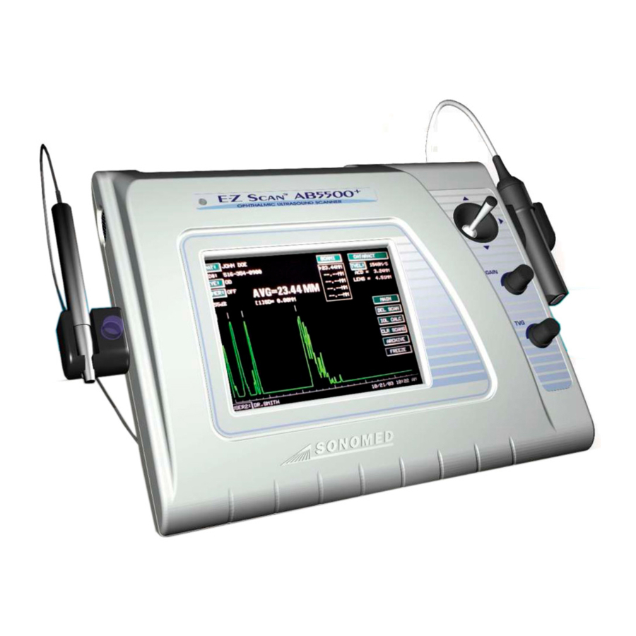
1-800-227-1285. General Description The E-Z Scan 5500+ series is the latest general ophthalmic biometry instrument introduced by the industry leading Sonomed. The series consists of two different models: 1.1 E-Z Scan B5500+ This B-Scan system allows for measuring a two-dimensional image of an eye along one plane. -
Page 5: Theory Of Operation
2.2 B-Scan Function Theory of Operation The operation of the B-Scan is similar to a radar operation. A short ultrasound wave is produced by a transducer and sent to the eye. Part of the energy of that wave is reflected back to the transducer from various 2.1 A-Scan Function One of the major applications of A-Scan is structures of the eye (lens, retina, etc.). -
Page 6: System Components
Power On position. In the Off position the LED will not illuminate. DC Input Port Interfaces to the Sonomed AC Adapter, 15 VDC @ 2.0 A, Part No. 9200-1409-1A RS 232 Port Connector located on the rear of the unit. -
Page 7: System Specifications
System Specifications 4.1 Regulatory Requirements The E-Z Scan 5500+ series of instruments Weight: 2.4 kg (5.25 lbs) shall meet and comply with the following Enclosure: Plastic, off-white color, regulatory requirements: internal EMC shielded * European Medical Device Directive 4.5 Electrical (MDD 93/42/EEC) The E-Z Scan 5500+ series shall be powered * CE mark including EMC "residential... -
Page 8: Display
System Specifications, con’t 4.8 Display Type: TFT Active Matrix Color LCD with touch screen overlay (262,144 colors) Resolution: 640 pixels (H) x 480 pixels (V) Dimensions: 6.5” (17cm) Diagonal High Luminance (250:1) 4.9 Printer Model: Sony UP-890MD Type: Video printer Paper Size: Roll paper Width: 110 mm (4.3") Diameter: 50 mm (2.0") -
Page 9: A-Scan System Specifications
A-Scan System Specifications 5.7 IOL Analysis Standard Programs: Binkhorst Regression-II 5.1 Calibration Calibration Mode: User invoked mode, will Theoretic-T confirm proper functioning using a test Holladay target Hoffer-Q Calibration Distance: 10.0 mm ± 0.1 mm Haigis (optional) Gain Control: Manual or automatic gain selection. - Page 10 A-Scan System Specifications Con’t Memory: Stores 5 scans and measurements, selected formula, IOL constants and user name. Report Data: Patients Name, ID#, Eye examined, K-readings, User Name, Date & Time. Live A-Scan Display Axial length, anterior chamber depth, and lens thickness measurements for each scan. Axial length average and standard deviation for up to 5 scans.
-
Page 11: B-Scan System Specifications
B-Scan System Specifications 6.1 Examination Modes: B-only 6.13 Typical Ultrasonic Intensities in tissue: B-scan: (autoscanning) 0.881 mW/cm SPTA 6.2 Display Scale: Electronic Markers @ 11.45 W/cm SPPA: 2.0mm Intervals 0.151 Ultrasonic Power 0.133 mW Measurement Accuracy Electronic: ±0.0484 mm 6.14 General Specifications / Features Clinical: ±0.1mm Maintains... -
Page 12: Trouble Shooting B5500
Trouble Shooting B5500+ 7.1 Factory Defaults Reset It is recommended that the unit be turned OFF before starting this procedure to ensure that clear microprocessor is reset. Turn the unit on. The unit will display the screen as shown in figure #1. Touch the B-SCAN field, the unit will display the screen as shown in figure #2. - Page 13 Trouble Shooting B5500+ con’t. Fig. 4 Fig. 5 Fig. 6 Doc# 0300-1903-3A page...
-
Page 14: Touch Screen Calibration
3mm of the pressed points. If the green response points are not displayed beneath the pressed points, Fig. 8 contact the Sonomed service department. Touch the DONE field, to return to the Calibration & Test screen (figure #4). Fig. 9... -
Page 15: Rgb Fill
( not spots of mixed colors or black pixels) If the screens are not completely Red, Green or Blue, contact the Sonomed service department. Press the touch screen in any spot for... -
Page 16: Joystick Alignment
If the Joystick can not be adjusted, call the Sonomed service department. 7.6 Rotary Encoder To Verfiy that the Rotary Encoders 0 and 1 are working properly, repeat the first several steps in the Factory Defaults Restore section until the unit displays the Calibration &... -
Page 17: System Information
The full range of numbers should be 0 – 255 in increments of 1. If the Encoder does not increment properly, replace the encoder, or call the Sonomed service department. 7.10 System Information To verify the System Information version, repeat the first several steps in the Factory Defaults Restore section until the unit displays the Calibration &... - Page 18 Scan vector reaches the top pattern and the Fig. 16 unit will display the screen shown in figure # 21. If any of the screens do not appear as shown, contact the Sonomed service department. Fig. 17 Fig. 18 Doc# 0300-1903-3A page...
- Page 19 Trouble Shooting B5500+ con’t. Fig. 19 Fig. 20 Fig. 21 Doc# 0300-1903-3A page...
-
Page 20: Cal Pattern Distance Test
Trouble Shooting B5500+ con’t. 7.9 Cal Pattern Distance Test Repeat the first several steps in the Factory Defaults Restore section until the unit displays the Calibration & Test screen (figure #4). Touch the CAL PATTERN field and the unit will display the screen as shown in figure #22. -
Page 21: Cal Pattern Area Test
These measurement are based upon a velocity of 1632 M/s. If any of the screens do not appear as shown, contact the Sonomed service department. 7.10 Cal Pattern Area Test Repeat the first several steps in the Factory Defaults Restore section until the unit displays the Calibration &... - Page 22 Trouble Shooting B5500+ con’t. Fig. 28 Fig. 29 Fig. 30 Doc# 0300-1903-3A page...
-
Page 23: Losing Date, Time And User Information
Trouble Shooting B5500+ con’t. 7.11 Losing date, time, user information It is recommended that the unit be OFF before starting this procedure. To replace the battery perform the following steps. Turn the unit off. Remove the four screws located on the bottom of the unit. -
Page 24: Unit Does Not Turn On
Trouble Shooting B5500+ con’t. 7.12 Unit does not Turn on Verify that the A.C. outlet has power. Using a voltmeter, verify that the E-Z Scan A.C. adapter P/N: 9200-1409-1A measures approximately 15Vdc at no load, or 15Vdc under load between J4 pin 1 and ground. 7.13 Rear Connector Descriptions figure rear... -
Page 25: Trouble Shooting A/B5500
The red LED on the tip of the A-Scan probe should be lit. If the LED is not lit, try a backup A-Scan probe. If the LED remains unlit, refer to section 8.5 or call Sonomed technical support. Touch the A-SCAN field and the unit will display the screen as shown in figure #37. -
Page 26: Measure
74 dB, and then perform a direct contact A-Scan. The unit will display the screen as shown in figure #41. If you can not obtain an image as shown, refer to section 8.4 and 8.5 or call Sonomed technical support. Losing date, time... -
Page 27: A-Scan Pcb
Trouble Shooting A/B5500+ Con’t 8.4 A-Scan PCB Turn unit off. Remove the four screws that secure the top cover. Verify that there are no broken wires (A) on the A-Scan Lemo connector and that the connector is seated properly (B) as shown in figure #42. -
Page 28: A-Scan Probe Cable Replacement
Trouble Shooting A/B5500+ Con’t 8.5 A-Scan Probe Cable replacement Order Sonomed Triax cable, Part number CA08-9901-44. Strip the outer insulating jacket from the cable and push the braided shield down (outer shield) as shown in figure #45. Carefully remove the cable within as shown in figure #46. - Page 29 Trouble Shooting A/B5500+ Con’t Slide the A probe housing onto the new cable and place a section of shrink tubing over the cable. Prep this end of the cable as before. Place a section of shrink tubing over the outer shield conductor and solder to pin 5 as shown in figure #50 (the shink tubing should prevent this conductor from touching the others).
-
Page 30: Routine Maintenance
Routine Maintenance The maintenance described below should be a soft cloth dampened with a mild detergent performed routinely so that the E-Z Scan is solution. always operating in a safe and reliable CAUTION manner. Calibration check and probe Never use strong solvents such as benzene, examination, etc. -
Page 31: Storage
Routine Maintenance, con’t 5. Carefully examine the probe tip for any Do Not autoclave the probe or cable. chipping or rough edges that may injure the cornea. After cleaning, rinse the end of the probe 6. If applicable, examine the "Soft-Touch" thoroughly with clean water to remove all mechanism of the A-probe to ensure that it traces of the liquid used. -
Page 32: Unit Assembly
Top Cover Bill of Materials FIND PART NUMBER COMPONENT DESCRIPTION 5550-1511-1A TOP COVER 5550-1413-1A LCD DISPLAY 5550-1421-1A POWER LED SW08-0001-43 TOUCH SCREEN 5550-1513-1A B-PROBE HOLDER 5550-1415-1A ENCODERS AND JOYSTICK ASSEMBLY 5500-2202-1A TOP OVERLAY: FOR B-5500+ (PRODUCT NAME) 5500-2202-2A FOR A/B-5500+ HW35-7250-60 KNOB ASSEMBLY HW28-7150-81... -
Page 33: Top Cover Assembly Drawing
Top Cover Assembly Drawing Doc# 0300-1903-3A page... -
Page 34: Bottom Cover Bill Of Materials
Bottom Cover Bill of Materials FIND PART NUMBER COMPONENT DESCRIPTION 5550-1510-1A BOTTOM COVER 5550-1401-1A MOTHERBOARD (B-5500+ AND A/B-5550+) 5550-1406-1A BAIL STAND 5550-1407-1A INPUT/OUTPUT CONNECTORS PANEL 5550-1408-1A PROBE PANEL (B-5500+) 5550-1408-2A PROBE PANEL (A/B-5500+) 5550-1409-1A FAN AND GRILL SUPPORT 5550-1503-1A BAIL STAND TRAY 5550-1502-1A SPRING CLIP HW40-6512-74... -
Page 35: Bottom Cover Assembly Drawing
Bottom Cover Assembly Drawing Doc# 0300-1903-3A page... -
Page 36: Accessories Bill Of Materials
Accessories Bill of Materials FIND PART NUMBER COMPONENT DESCRIPTION 5550-1403-1A (or) UNIT (B-5500+) 5550-1403-2A (or) UNIT (A/B-5500+) 5550-1403-3A UNIT (A-5500+) MC01-0001-99 TOUCH SCREEN STYLUS AC ADAPTOR: 15V @ 2A: 9200-1409-1A (or) NORTH AMERICA; JAPAN; TAIWAN 9200-1409-2A (or) EUROPE 9200-1409-3A (or) UNITED KINGDOM 9200-1409-4A AUSTRALIA... -
Page 37: Accessories Drawings
Accessories Drawing Doc# 0300-1903-3A page... -
Page 38: Schematics
Clock Generator Schematic SCHEMATIC INSIDE FOLDER BEHIND THIS TITLE PAGE Doc# 0300-1903-3A page... -
Page 39: Front End Interface
Front End Interface Schematic SCHEMATIC INSIDE FOLDER BEHIND THIS TITLE PAGE Doc# 0300-1903-3A page... -
Page 40: Power Supply
Power Supply Schematic SCHEMATIC INSIDE FOLDER BEHIND THIS TITLE PAGE Doc# 0300-1903-3A page... -
Page 41: Pulser Receiver
Pulser Receiver Schematic SCHEMATIC INSIDE FOLDER BEHIND THIS TITLE PAGE Doc# 0300-1903-3A page... -
Page 42: Servo Controller
Servo Controller Schematic SCHEMATIC INSIDE FOLDER BEHIND THIS TITLE PAGE Doc# 0300-1903-3A page... -
Page 43: System Processor
System Processor Schematic SCHEMATIC INSIDE FOLDER BEHIND THIS TITLE PAGE Doc# 0300-1903-3A page... -
Page 44: Video Interface
Video Interface Schematic SCHEMATIC INSIDE FOLDER BEHIND THIS TITLE PAGE Doc# 0300-1903-3A page... -
Page 45: Xilinx Configuration
Xilinx Configuration Schematic SCHEMATIC INSIDE FOLDER BEHIND THIS TITLE PAGE Doc# 0300-1903-3A page... -
Page 46: Xilinx Power/Decouple
Xilinx Power/Decouple Schematic SCHEMATIC INSIDE FOLDER BEHIND THIS TITLE PAGE Doc# 0300-1903-3A page... -
Page 47: Xilinx Ram Interface
Xilinx RAM Interface Schematic SCHEMATIC INSIDE FOLDER BEHIND THIS TITLE PAGE Doc# 0300-1903-3A page... -
Page 48: Xilinx Test Points
Xilinx Test Ports Schematic SCHEMATIC INSIDE FOLDER BEHIND THIS TITLE PAGE Doc# 0300-1903-3A page...
Need help?
Do you have a question about the E-Z Scan AB5500 Plus and is the answer not in the manual?
Questions and answers