Advertisement
Quick Links
Advertisement

Related Manuals for KOOLAIR KOOLCOM

Summary of Contents for KOOLAIR KOOLCOM
- Page 1 KOOLCOM Motor-driven fire damper monitoring systems www.koolair.com...
-
Page 2: Table Of Contents
KOOLCOM KOOLCOM fire damper monitoring system CONTENTS Description General system schematic diagram System components KHUK connection schematic diagram Accessories Coding Environment and guarantee... -
Page 3: Description
KOOLCOM KOOLCOM fire damper monitoring system. Introduction KOOLCOM is an electronic control system for fire dampers that allows the condition and functionality of each fire damper to be periodically and automatically monitored and checked. It can also close the dampers should the fire alarm be activated. -
Page 4: General System Schematic Diagram
KOOLCOM General schematic diagram of the KOOLCOM monitoring system. Note: If the KHUK alarm input is connected to a fire panel, the modbus wiring between KHUK and DCUs, and between KHUK and the BMS, must be flame retardant. (Possible connections for 1 to 247 KHUKs). -
Page 5: System Components
System components. Damper Control Unit (DCU 1CH) The DCU contains the control electronics for the different fire dampers. KOOLCOM offers two models which allow either 1, or up to 4 dampers to be controlled by the same device. DAMPER CONTROL UNIT 1 CHANNEL (DCU 1CH) - Page 6 KOOLCOM Specifications (DCU 1CH) • Maximum load on the damper motor output: 24V (AC/DC) model: 230V AC model: 0.5A • Maximum load in the detection zone: 100mA • Maximum power consumption (without detector or damper): 24V (AC/DC) model: 100mA@24V 0.72W...
- Page 7 KOOLCOM Damper Control Unit 1 channel (DCU 1CH) Input Binary ModBus ModBus 24 AC/DC Default load address termination values activation Direct Universal Smoke Connection Cable tie connection connection detector ModBus 230v Belimo / Siemens Input connector 230v AC The universal damper connection is a 5-wire connection: o Contacts: - S4+S1: can be connected inside the damper.
- Page 8 KOOLCOM Damper Control Unit 1 channel connection (DCU 1CH): two versions (24V / 230V) 100-DCK300 - 24V: Power 100-DCK400 - 230V: Power 220V ModBus IN KHUK ModBus OUT DCUs DETECTOR Contacts Motor Power supply 230V (cable tie is essential) or 24V. 2 wires.
- Page 9 ModBus, allow them to be automated and controlled They are integrated in the KOOLCOM system for controlling and supervising motor-driven fire dampers and four smoke detectors (zones). This system is completed with KHUK units (KoolCom Hub Unit KoolAir), which allow DCUs to be grouped (1CH or 4CH) in sets of 32 units, in addition to connecting the colour, touch screen consoles.
- Page 10 KOOLCOM Specifications (DCU 4CH) • Maximum joint load on the damper motor outputs: 24V (AC/DC) model: 230V AC model: 0.5A • Maximum load in the detection zone: 100mA per zone / 300 mA combined • Maximum consumption (without detector or damper):...
- Page 11 KOOLCOM Damper Control Unit 4 channel (DCU 4CH) INPUT POWER 230V Model 230V AC ALR DAMPER DRY CONTACT OUTPUT activated in the event of an alarm FAN DAMPER DRY CONTACT OUTPUT supply, can be configured for extract MODBUS ADDRESS CONFIGURATION...
- Page 12 KOOLCOM Damper Control Unit 1 channel connection (DCU 4CH): two models (24V / 230V) 100-DCK500 - 24V AC/DC: 100-DCK600 - 230V AC: Power Power 230V DAMPERS DAMPERS Contacts Contacts Motor Motor Contacts Contacts Motor Alarm input Motor Exterior ModBus ModBus OUT...
- Page 13 The KHUK is a Modbus hub device that occupies a single address, allows up to 128 fire dampers and 128 smoke detectors (32 DCU-4CH units) to be managed. Each KHUK has: - 1 connection to the Koolcom console. - Direct connection to fire panel: • Alarm activation input.
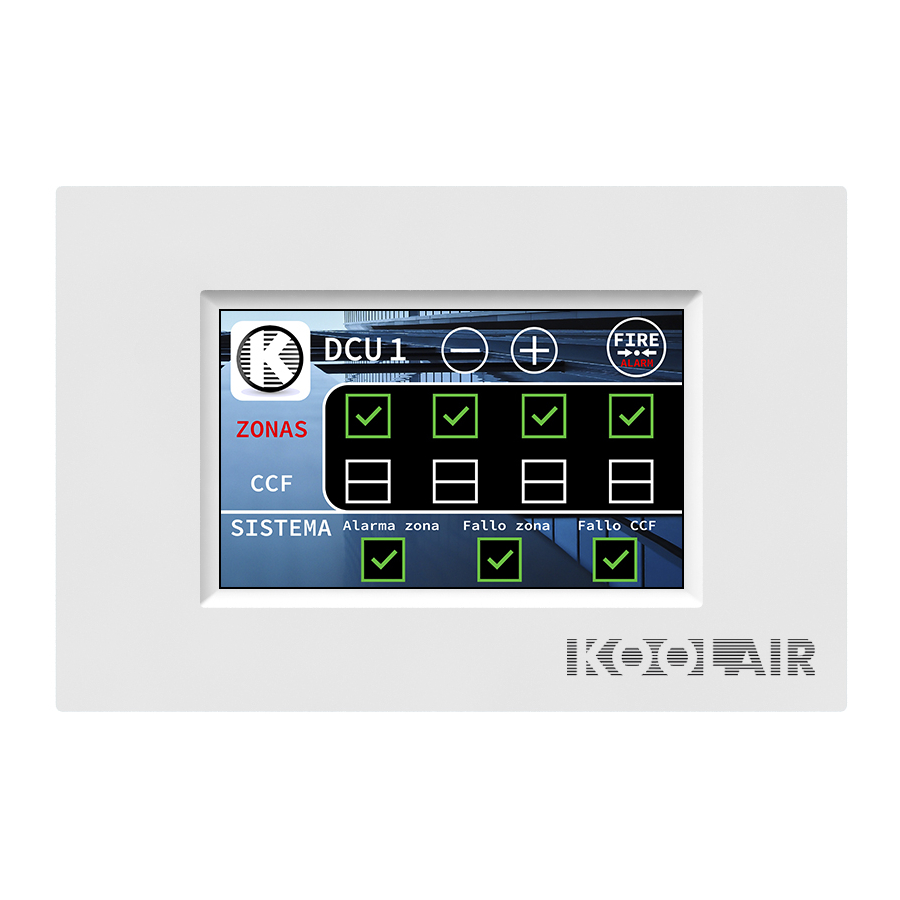
- Page 14 KOOLCOM System components. Graphic console The KOOLCOM graphic console allows monitoring and control of DCUs connected to the associated KHUK, facilitating the monitoring and control of fire dampers and smoke detectors (zones). The console allows information on the overall status of the system and each connected DCU to be displayed, as well as the basic parameters to be configured and managed.
-
Page 15: Khuk Connection Schematic Diagram
KOOLCOM KHUK connection schematic One KHUK has connections for up to 32 DCUs (maximum 128 dampers and 128 detectors), the wall mounted graphic console and a BMS. It can interact with the central fire alarm system with external alarms going to the KHUK and detected alarm coming from the KHUK. - Page 16 KOOLCOM KHUK AND DCUs Three wires with polarity that connect exclusively to the DCUs. The KHUK contains the MODBUS termination. By inserting the MBUS TERM bridge into the furthest DCU, the two necessary terminations are achieved. Different DCU models (DCU- 1CH and DCU-4CH) can be mixed in the same bus.
- Page 17 KOOLCOM KHUK and alarms N.O. Alarm CENTRAL CENTRAL Output FIRE ALARM FIRE ALARM C RELE ON RELE Reset KHUK alarm Power supply KHUK Alarm activation N.O. Alarm Relay Output: Volt-free contacts with a Fire Alarm and Reset Input: When the +24V from the...
-
Page 18: Accessories
KHUK and the different DCUs to be expanded and isolated. USB-MODBUS Interface Allows the KOOLCOM system and a computer to be connected if there is no integrated RS485 port. -
Page 19: Coding
DESCRIPTION 100-UCK000 KOOLCOM HUB 100-TCK000 KOOLCOM GRAPHIC DISPLAY 100-DCK500 DAMPER CONTROL UNIT KOOLCOM, 4 DAMPERS, 24V (AC/DC) 100-DCK600 DAMPER CONTROL UNIT KOOLCOM, 4 DAMPERS, 230V AC 100-DCK300 DAMPER CONTROL UNIT KOOLCOM, 1 DAMPER, 24V (AC/DC) 100-DCK400 DAMPER CONTROL UNIT KOOLCOM, 1 DAMPER, 230V AC... -
Page 20: Environment And Guarantee
Any part or product changed becomes the property of KOOLCOM. The remedied defect of the repaired product is guaranteed for a period of 6 months from the date of repair. - Page 21 KOOLCOM THIS CATALOG IS INTELLECTUAL PROPERTY. The partial or total reproduction of its contents is forbidden without the express and authoritative authorisation of KOOLAIR, S.L. CEN-KOOLCOM-1117-00...
- Page 22 KOOLAIR, S.L. Calle Urano, 26 Poligono industrial nº 2 – La Fuensanta 28936 Móstoles - Madrid - (España) Tel: +34 91 645 00 33 Fax: +34 91 645 69 62 e-mail: info@koolair.com www.koolair.com...
Need help?
Do you have a question about the KOOLCOM and is the answer not in the manual?
Questions and answers