
Related Manuals for Trick-tools Hougen-Ogura PUNCH PRO 75004PR

Summary of Contents for Trick-tools Hougen-Ogura PUNCH PRO 75004PR
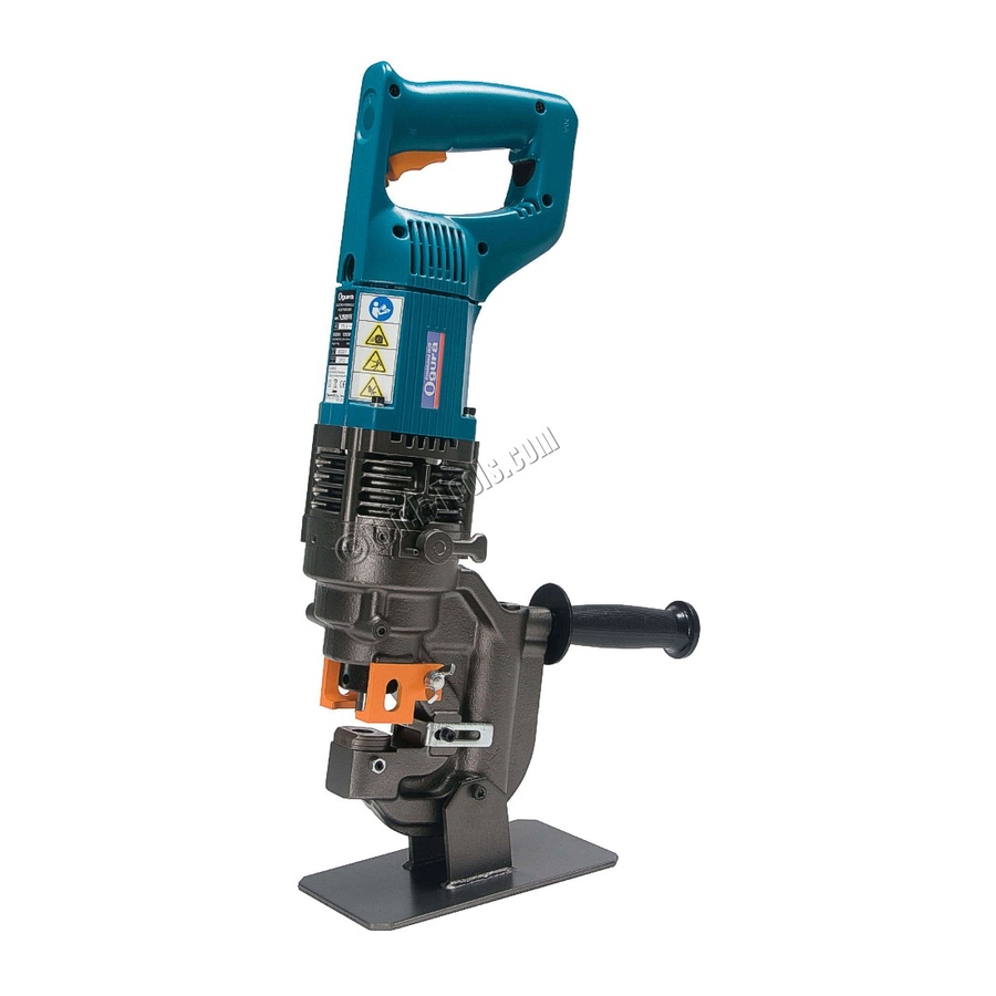
- Page 1 75004PR PUNCH PRO ™ ELECTRO-HYDRAULIC HOLE PUNCHER operator’s manual COVERS HOLE PUNCHER PART NUMBERS 0754102 & 0754202 OM75004PR0815 Printed in U.S.A.
- Page 2 Electro-Hydraulic Hole Punch Models 0754102 & 0754202 Congratulations on your purchase of the Hougen -Ogura™ Electro-Hydraulic Hole Puncher. Your model is ® designed to produce superior holes quickly and efficiently. Through constant innovation and development, Hougen is committed to provide you with hole producing tools and products to help you be more productive. Before attempting to operate your new hole puncher, please read all instructions first.
-
Page 3: Important Safety Instructions
Important Safety Instructions WarnInG 1. Before use, read this Instruction Manual thoroughly. 14. Do not overreach. Do not expose the charger and battery to rain or use Keep proper footing and balance at all times. them in damp or wet locations, as this may cause 15. -
Page 4: Principals Of Operation
75004PR CONTENTS Hydraulic Oil 75376 76341 9/16" Diameter Punch 9/16" Diameter Die - Type SB - For material 5/64" to 3/8" 76323 Spanner 75771 10mm Open End Wrench 75771 Foot Switch (115V) 75110 Foot Switch (230V) 76479 Foot Switch (230V, Type I) 76480 Work Stand 76456... -
Page 5: Trigger Switch
FOOT SWITCH Although the foot switch is guarded against inadvertent The trigger switch should be locked on only when ready operation, it is best to position the foot pedal away from to punch. Release the trigger switch immediately after normal standing position. Place it in a position that punching to prevent operation by inadvertent actuation requires deliberate effort to reach and activate the switch. - Page 6 REMOVING AND INSTALLING ROUND PUNCHES Prior to removing a punch, jog the punch piston down Place your punch into the retaining nut, properly until it puts pressure on a piece of material that is of the align the punch within the punch piston and hand appropriate thickness.
- Page 7 REMOVING AND INSTALLING OBLONG PUNCHES OBLONG PUNCHES CAUTION Before replacing the punch and die, ensure that the machine is disconnected from its power source to prevent accidental operation and personal injury. 1. Be sure that the punch piston is fully retracted and remove the strippers to make access to the parts easier.
- Page 8 SELECTING PROPER DIES Proper die selection is essential. Other than the obvious flat dies, but "I" -beams and most channels which necessity of matching shaped punches and dies, there are have a 2-in-12 taper require the use of special two other basic selection factors that must be considered. 9-1/2 degree angled dies.
-
Page 9: Operating Procedures
OPERATING PROCEDURES 1. Before make any adjustment, turn off the power supply and unplug the power cord. 2. Check the position for punching and adjust the slide stopper to the required distance. The slide stopper, which is set to hold the hole puncher at a constant distance from the edge of the workpiece, is held in place by one or two socket head cap screws. -
Page 10: Maintenance
MAINTENANCE CAUTION Keep the air hole at the end of the C frame clear of dirt and obstructions. The air hole has to be open in order to control the hydraulic pressure. CAUTION Do not undo or remove the three screws in the drawing on the left. - Page 11 PUNCH AND RETAINING NUT Punch IMPORTANT NOTE PERIODICALLY CHECK THE RETAINING NUT, MAKING SURE IT IS TIGHTENED PROPERLY. O-Ring HELPFUL HINTS FOR HOLE PUNCHING If the position is not satisfactory, open the manual return Each of the punches is provided with a sharp point at its valve to retract the punch for another attempt.
-
Page 12: Parts Breakdown
PARTS BREAKDOWN... - Page 13 MODEL 75004PR PARTS LIST Det # Part # Description Det # Part # Description 76427 Needle Holder A 76460 Slide Stopper 76428 Needle Bearing 75157 Washer WM5 76429 Stop Ring 76402 Bolt HB5 x 12 76430 Pump Case 75063 Grip Handle 75090 Seal Washer 75175...
- Page 14 PUNCHES AND DIES FOR 75004PR ROUND PUNCH MATERIAL OBLONG PUNCH MATERIAL Size Size Part Part Part Part Thickness Style Size Thickness Style Size Nominal Actual Metric Nominal Actual Metric 5/64 (.078) to 1/8 (.125) 5/64 (.078) to 1/8 (.125) 1/4" F, A, H Die 15/64 SA 76308...
-
Page 15: Troubleshooting
TROUBLESHOOTING " "... - Page 16 Commercial / Industrial Limited Warranty Hougen Manufacturing, Incorporated warrants its Portable Magnetic Drills, Electro-hydraulic Hole Punchers for a period of (1) one year and other products for ninety (90) days from date of purchase against defects due to faulty material or workmanship and will repair or replace (at its option) without charge any items returned.
Need help?
Do you have a question about the Hougen-Ogura PUNCH PRO 75004PR and is the answer not in the manual?
Questions and answers