Table of Contents
Advertisement
Available languages
Available languages
INSTALLER: PLEASE FAMILIARIZE YOURSELF WITH THIS MANUAL BEFORE PROCEEDING WITH THE
INSTALLATION. LEAVE THIS MANUAL WITH THE APPLIANCE FOR FUTURE REFERENCE.
CONSUMER: RETAIN THIS MANUAL FOR FUTURE REFERENCE.
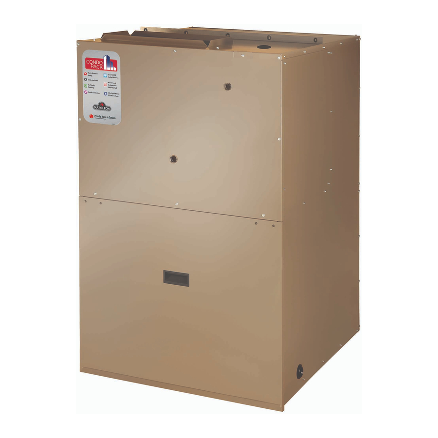
THRU-THE-WALL PACKAGED UNIT
CONFORMS TO ANSI/UL STD. 1995,
CERTIFIED TO CAN/CSA STD. C22.2 NO. 236 AND
ANSI/AHRI STD. 390
9700539
WARNING
!
ELECTRICAL SHOCK, FIRE OR EXPLOSION
HAZARD
FAILURE TO FOLLOW SAFETY WARNINGS
AND INSTRUCTIONS EXACTLY COULD
RESULT IN SERIOUS INJURY, DEATH OR
PROPERTY DAMAGE.
INSTALLATION AND SERVICE MUST BE
PERFORMED BY A QUALIFIED INSTALLER.
IMPROPER INSTALLATION, ADJUSTMENT,
ALTERATION, SERVICE, OR MAINTENANCE
CAN CAUSE INJURY OR PROPERTY
DAMAGE. REFER TO THIS MANUAL AND
CONSULT A SERVICE AGENCY FOR AD-
DITIONAL INFORMATION.
UNIT CONTAINS R-410A REFRIGERANT AND
POE COMPRESSOR OIL.
USE ONLY R-410A REFRIGERANT AND
APPROVED POE COMPRESSOR OIL.
PROPER SERVICE EQUIPMENT IS
REQUIRED. USE ONLY R-410A APPROVED
SERVICE EQUIPMENT.
FOR YOUR SAFETY, DO NOT STORE OR
USE GASOLINE OR OTHER FLAMMABLE
VAPORS AND LIQUIDS IN THE VICINITY OF
THIS OR ANY OTHER APPLIANCE. SUCH
ACTIONS COULD RESULT IN PROPERTY
DAMAGE, PERSONAL INJURY, OR DEATH.
CAUTION
!
INSTALLATION SHALL BE MADE IN ACCOR-
DANCE WITH THE REQUIREMENTS OF THE
LOCAL UTILITY AND OTHER AUTHORITIES
HAVING JURISDICTION, THE NATIONAL
ELECTRICAL CODE IN THE UNITED STATES
AND THE CANADIAN ELECTRICAL CODE
CSA C22.1 PART 1 (LATEST EDITION) IN
CANADA. ANY ALTERATION OF INTERNAL
WIRING WILL VOID CERTIFICATION AND
WARRANTIES.
INSTALLATION AND OPERATING
WITH ELECTRIC HEATING & COOLING
!
THE HIGH EFFICIENCY THRU-THE-WALL
SELF CONTAINED HEATING & COOLING UNIT
• 11 EER
• Up to 24000 BTU/h Cooling
• Up to 15kW Electric Resistance Heating
• R-410A Refrigerant System
• Micro-Channel Condenser and Evaporator Coils
• Removable heating module
• Pre-wired and pre-charged
• Plug-and-play installation and service
• Individual metering and control for each unit
• Installation and service must be performed by a qualifi ed
installer or service agency.
• Before servicing, disconnect all electrical power to the unit.
!
• When servicing controls, label all wires prior to
disconnecting. Reconnect wires correctly.
• Verify proper operation after servicing.
• Do not store or use gasoline or other fl ammable vapors
and liquids in the vicinity of this or any other appliance.
MANUFACTURER RESERVES THE RIGHT TO DISCONTINUE, OR CHANGE AT ANY TIME,
SPECIFICATIONS OR DESIGNS WITHOUT NOTICE AND WITHOUT INCURRING OBLIGATIONS.
Wolf Steel Ltd., 24 Napoleon Rd., Barrie, ON, L4M 0G8 Canada /
103 Miller Drive, Crittenden, Kentucky, USA, 41030
• Phone (866) 820-8686 • hvac@napoleon.com •
INSTRUCTIONS
P-E SERIES
IMPORTANT
!
• www.napoleon.com •
IOM
11 EER
2.0 ton
!
W415-2288 / 08.29.2019
Advertisement
Chapters
Table of Contents
Troubleshooting

Summary of Contents for Napoleon Condo Pack
- Page 1 SPECIFICATIONS OR DESIGNS WITHOUT NOTICE AND WITHOUT INCURRING OBLIGATIONS. CSA C22.1 PART 1 (LATEST EDITION) IN Wolf Steel Ltd., 24 Napoleon Rd., Barrie, ON, L4M 0G8 Canada / CANADA. ANY ALTERATION OF INTERNAL 103 Miller Drive, Crittenden, Kentucky, USA, 41030 WIRING WILL VOID CERTIFICATION AND •...
-
Page 2: Table Of Contents
AIR CONDITIONING TROUBLESHOOTING ........................50 ADJUSTING SYSTEM CHARGE ............................52 HEATING MODULE TROUBLESHOOTING ........................53 9. P-E CONDO PACK REPLACEMENT PARTS LIST ..................54 P-E CABINET WITH CONDENSER FAN AND INDOOR BLOWER ASSEMBLY ..............54 COOLING SECTION PARTS LIST ............................56 P-E HEATING MODULE ............................... -
Page 3: Model Nomenclature
Rev. A (Cabinet Revision A) 2. OVERVIEW These instructions cover the installation of the Condo Pack, which consists of three separate sections: the wall sleeve, the cabinet with the air conditioning (AC) section and the furnace module. Instead of replacing the complete system, the furnace module can be partially or fully removed for servicing. -
Page 4: Safety
3. SAFETY Only trained service technicians familiar with standard service instructions and training material shall install, service, and repair these units. Improper installation, adjustment, alteration, service, maintenance, or use can cause explosion, fire, electrical shock, or other conditions which may cause death, personal injury, or property damage. - Page 5 IMPORTANT A DIRTY, CLOGGED AIR FILTER MUST BE CLEANED OR REPLACED. IF NOT CLEANED OR REPLACED PROMPTLY, THE AUTO-RESET HIGH TEMPERATURE LIMIT SWITCH WILL CYCLE THE HEATING ELEMENTS ON AND OFF, WHICH COULD REDUCE THE LONGEVITY OF THE HEATING ELEMENTS AND REDUCE THE SYSTEM PERFORMANCE. A SEVERELY CLOGGED FILTER, INLET OR OUTLET DUCT COULD CAUSE FAILURE OF THE NON-RESETTABLE HIGH TEMPERATURE LIMIT SWITCH, AT WHICH POINT A QUALIFIED SERVICE TECHNICIAN MUST BE CONTACTED TO PERFORM NECESSARY SERVICE.
-
Page 6: Safety Rules
SAFETY RULES 1. For starting up and shutting down the unit refer to “6. STARTUP AND SHUTDOWN”. 2. Store this unit only in dry indoor locations (protected from weather and extreme cold temperatures). 3. DO NOT install this unit outdoors or in a mobile home, trailer or recreational vehicle. This appliance is not designed/ certified for these installations. -
Page 7: Installation
4. INSTALLATION WALL SLEEVE The unit is shipped in one package, completely assembled CABINET and wired. The air conditioning condensate drain is shipped separately with SUPPLY OUTLET the unit for field install. ELECTRICAL SLOT If any damage is found, proper notation should be made on the carrier’s freight bill. -
Page 8: Unit Dimensions
UNIT DIMENSIONS 16" 16 " 2 " 8 " 8 " 8" SUPPLY OUTLET ELECTRICAL CONNECTION 28" 5 " 29" Control Board Inspection Window 8 " 8 " MIN DRAIN FLOOR 16 " 16 " " 8 " 16 " 4 "... -
Page 9: Unit Location And Clearances
Buildings taller than six stories will have the same distance parameters as six-story buildings. • If three or more adjacent walls form an air shaft with Condo Pack units facing each other in each wall, the distance between opposite walls should be increased by 20%. - Page 10 THE AREA AROUND THE UNIT MUST BE KEPT CLEAR AND FREE OF ALL COMBUSTIBLE MATERIALS INCLUDING GASOLINE AND OTHER FLAMMABLE VAPORS AND LIQUIDS. THE HOMEOWNER SHOULD BE CAUTIONED THAT THE CONDO PACK AREA MUST NOT BE USED AS A CLOSET OR FOR ANY OTHER STORAGE PURPOSE. H3.7. 1 This design is certified for thru-the-wall installation only.
- Page 11 4.2.1 Minimum Clearances The minimum clearances required for installation and accessibility are shown below. These clearances should be followed unless otherwise approved by the manufacturer. FIG. 4.2.1.A W415-2288 / 08.29.2019...
- Page 12 FIG. 4.2.1.B W415-2288 / 08.29.2019...
-
Page 13: Packaged Unit Preparation
PACKAGED UNIT PREPARATION NOTE • THIS UNIT MUST BE INSTALLED IN ACCORDANCE WITH ALL APPLICABLE CODES. • THIS UNIT IS APPROVED FOR THRU-THE-WALL INSTALLATION ONLY. • THESE INSTALLATION AND MAINTENANCE INSTRUCTIONS SHOULD BE LEFT WITH THE UNIT FOR FUTURE REFERENCE. Prior to installing the unit in the wall opening: 1. -
Page 14: Wall Sleeve Assembly And Installation
ITEM PART NAME MANUFACTURING DESCRIPTION PART NO Gasket D-Channel 28.9” long 12.5 feet GASKET, D-CHANEL EPDM (included in baggies provided with Condo Pack unit) W290-0256 Gasket D-Channel 44” long IMPORTANT DO NOT DISCARD ITEM #12 (TOP PANEL BRACKET, W080-1721). THIS BRACKET IS USED TO SECURE... - Page 15 Wall Sleeve Dimensions DIAGRAM (B) TWO DIFFERENT WALL SLEEVE MODELS ARE DEPICTED BELOW: • CWSMUA • CWSMUA19 NOTE: TO IMPROVE RIGIDITY AND REDUCTION IN VIBRATION WALL MOUNTING BRACKETS CAN BE USED TO AFFIX WALL SLEEVE TO BUILDING SUB STRUCTURE FROM INSIDE OR OUTSIDE OF THE BUILDING. ENGINEER/ARCHITECT TO CONSULT WITH CUSTOMER SOLUTIONS IF CLARIFICATION IS REQUIRED TO DETERMINE BRACKET LOCATION FOR SETTING THE DESIRED DEPTH...
- Page 16 4.4.1 Wall Sleeve Assembly Place Base part (2) on the fl oor and attach Right Side Panel (3): a. Position Base Panel (2) to seat behind fl anges on the Side Panel (3). b. Bring together panel clips and the openings (FIG.
- Page 17 Squaring Brace (11) across the wall sleeve, as shown in the FIG. 5. 10” NOTE: Do not remove Squaring Braces (10) and (11) from the wall sleeve if you do not plan to install the Condo Pack unit immediately. 10” 10” 10” 10”...
- Page 18 4.4.2 Wall Sleeve Installation WARNING INSTALLATION CREW MUST ADHERE TO ALL LOCAL/NATIONAL SAFE WORK PRACTICES INCLUDING EMPLOYING APPROPRIATE FALL ARREST EQUIPMENT When installed, the Wall Sleeve must protrude Finished Wall 1/2” MIN. to 1” MAX. beyond the exterior fi nished wall Flashing PROTRUDE to allow proper water evacuation through the drain holes...
- Page 19 NOTE: The following support bracket locations are for installations where the wall sleeve is installed from the OUTSIDE of the building. For installations where the wall sleeve is installed from the INSIDE of the building, the Side Support Brackets (5) need to be mounted on INTERIOR wall, so they will need to be relocated on the wall sleeve (new screw positions may need to be created depending of the type of wall construction).
- Page 20 Expanding Insulation Foam (FIG 13). Ensure parallel position between Wall Sleeve and wall opening. Wall Sleeve must be square for the Condo Pack to slide into it. b. Attach Wall Sleeve to the building: 1/4” GAP • Secure the support brackets to the wall in between the wall using fi ve screw holes on each side.
-
Page 21: Unit Support
Step 1: Construct a three sided box or a two sided frame to suffi ciently support Condo Pack weight (Fig 16A). An optional rectangular plywood with 9” x 25” Optional plywood board with ** Minimum platform depth 9”x25”... -
Page 22: Gasketing On Wall Sleeve
An additional vibration isolation material (must be non-combustible) may be used if required. d. Ensure that the platform connection to Condo Pack Return Air Opening is at least 24 1/8” x 8 1/4”. It must be aligned with return air opening on the base of the installed Condo Pack appliance. -
Page 23: Packaged Unit Installation
1. Verify that isolation grommets are installed in the five holes on the top mounting bracket. 2. Bring the Condo Pack as close as possible to wall opening (FIG. 4.6.A). Carefully slide the unit into the Wall Sleeve (refer to “4.4 Wall Sleeve Assembly and Installation”) so the front of the unit is in... - Page 24 4.7.1 SEALING: Wall Sleeve and Condo Pack Cabinet Fill the clearance space between the sleeve and the cabinet with non-hardening caulking compound or non-expanding insulation foam as a protection against the snow, water, SEAL moisture and air infi ltration. CORNERS...
-
Page 25: Ductwork
DUCTWORK 4.8.1 Supply Air Ducting IMPORTANT BOTH SUPPLY AND RETURN AIR MUST BE DUCTED TO THE APPLIANCE FROM ROOMS SEPARATE TO THE CLOSET ENCLOSURE HOUSING THE APPLIANCE. SUPPLY AIR DUCT (PLENUM) CONNECTION MUST BE AT LEAST THE SAME SIZE AS THE UNIT SUPPLY AIR OPENING. - Page 26 Return Air Duct through the opening. 4. Align the upper edges, adjusting the height. 5. Mount to the Condo Pack using four self- tapping screws provided. 6. Insert second part B and mount to extension part A using two screws from inside.
-
Page 27: Condensate Drain Connection
CONDENSATE DRAIN CONNECTION A properly functioning condensate trap provides discharge of water from the cooling coil drain pan, while the water seal (the water level maintained in the trap) prevents the fl ow of ambient air in or out of the unit. The pre-fabricated condensate drain connection hose (with integral P trap) for air conditioning section is included but not installed. -
Page 28: Electrical
It is NOT permissible to connect unit to accessories such as humidifier transformers, condensate pumps and electronic air cleaners. WARNING PROVIDE EACH CONDO PACK UNIT WITH ITS OWN SEPARATE ELECTRICAL CIRCUIT, MEANS OF CIRCUIT PROTECTION, AND ELECTRICAL DISCONNECT SWITCH. FOLLOW CURRENT NATIONAL ELECTRICAL CODE ANSI/NFPA 70, CSA C22.1 C.E.C. PART 1, AND STATE AND LOCAL CODES. - Page 29 5.1.3 Power Supply Installation Reducing Cover Plate ELECTRICAL Large SUPPLY SLOT SUPPLY OUTLET HEATING Medium MODULE SIDE FRONT PANEL ACCESS PANEL Electrical Slot COOLING SECTION Small Locate the Position the cover reducing plate Reducing Cover Plates: electrical supply slot over the electrical slot and secure Based on cable gauge, determine the on the top of cabinet enclosure.
- Page 30 5.1.4 Electrical Panel Power Cable BLACK THERMOSTAT BLACK Heater BLACK Ground Panel Connection BLACK GREEN BLACK Transformer POWER DISTRIBUTION BLOCKS Breaker Breaker Relay Relay BLACK BLACK BLACK WHITE Relay Low Voltage FUSE HOLDERS Fuse 2.5 A G W C Y/Y2 Terminal Block BLACK BLACK...
- Page 31 5.1.5 Wiring Diagrams 5.1.5.1 Heating Module Wiring Diagram W415-2288 / 08.29.2019...
- Page 32 * Certaines unités ont un moteur de ventilateur extérieur à deux vitesses. Reportez-vous au manuel pour la sélection de vitesse correcte. W385-1116/B 7.5” x 7.5” ARIAL REG WHITE BACKGROUND, BLACK INK CLASS IIIC - ADHESIVE BACKING, LAMINATE OVERLAY WATERPROOF, NONWATER SOLUBLE ADHESIVE NG SCHEMATIC CONDO PACK AIR CONDITIONING SECTION ED TITLE AND SUB-TITLE || 04.26.19_N.P. W415-2288 / 08.29.2019...
- Page 33 5.1.5.3 Blower Only (Lower Module) Wiring Diagram WIRING DIAGRAM / SCHÉMA DE CÂBLAGE SEE CONTINUING DETAIL ON UPPER MODULE WIRING DIAGRAM / VOIR LES DÉTAILS SUR LE SCHÉMA DE CÂBLAGE DU MODULE SUPÉRIEUR ECM X-13 MOLEX MOTOR SEE NOTE 1 CONNECTIONS 24V CONTROL SIGNAL TO...
-
Page 34: Removal Of Heating Module, Condenser Fan And Indoor Blower
REMOVAL OF HEATING MODULE, CONDENSER FAN AND INDOOR BLOWER NOTE: The number of breakers and relays on the control panel will vary depending on the heating capacity of the unit. “5.2.4 Electrical and Refer to Physical Data” HEATING MODULE NOTE: VESTIBULE If harness needs to be VESTIBULE... - Page 35 5.2.1 Heating Module Removal WARNING RISK OF ELECTRICAL SHOCK ! DISCONNECT POWER BEFORE INSTALLATION. Power Cables Disconnect power to unit. Remove power Remove the screws from the furnace cables. Pull down and remove the front panel. front panel. ground cable Squeeze the Squeeze the two tabs on the X13 two tabs on the...
- Page 36 Transformer Distribution Block Do not forget to remove the side screw #9. Fuse Block Side Screw Remove all 9 screws holding the heating module in, as shown in the this diagram (28). When sliding heating module back into the cabinet, make sure the module Transformer slides UNDER...
- Page 37 5.2.2 Condenser Fan Removal To remove condenser fan, heating module must be removed first. Refer to steps 1-16 shown in “Heating Remove two screws holding Module Removal”. Remove side manifold cover baffle. side manifold cover baffle. Remove rear manifold cover baffle. Remove 4 rear manifold screws (one from the top).
- Page 38 Thread the wiring back through Using four bolts, four washers Slide in condenser fan assembly. the hole of the module. and four locknuts, install fan back. Mount condenser fan shroud by installing 10 screws (3 on the top and 7 at the bottom). Make sure that insulation peace is not damaged.
- Page 39 5.2.3 Blower Removal Remove heating module. Refer to steps 1-16 from ”Heating Module Removal” section. Remove seven screws along the back. Remove 10 round head and 6 hex head screws. Remove top blower plate. Remove 10 screws from the front blower plate and electrical plate Remove Molex connector from the (with capacitor and contactor on it).
- Page 40 Install 10 screws to the front blower plate and electrical plate (with capacitor and contactor on it). Electrical plate Install electrical plate (with Lift and place blower down into cabinet. capacitor and contactor attached). Connect Molex connector to the Place top blower plate back into place.. front blower plate.
- Page 41 5.2.4 Electrical and Physical Data TABLE 4. * Models with A18A & A24A Air Conditioning have two speed condenser fan motor. Speed 1 is for A18A and Speed 2 is for A24A units. W415-2288 / 08.29.2019...
- Page 42 5.2.5 Low Voltage Wiring The thermostat and control wiring should be a minimum of 18 AWG copper. Excessive lengths of wire may result in enough voltage drop to impair the proper functioning of the furnace. For thermostat wires in excess of 25 feet (7.6m), use 16 AWG;...
-
Page 43: Startup And Shutdown
Single-pole, single-throw thermostats are not suitable for use with Condo Pack. Indoor blower motor speed for cooling and heating modes can be altered by changing the motor speed taps on the x13/Endura Pro Motor harness. -
Page 44: Sequences Of Operation
SEQUENCES OF OPERATION 6.2.1 Heating Cycle 1. When thermostat switch is set to heat, the terminals R&W get connected which will energize the indoor blower and all the relays for the heating elements immediately. 2. Relay 1, once energized, turns the first Heating element ON with up to 1 second delay. At the same time Relay 2 powers the rest of the heating elements with delay range from 1 to 8 seconds (applicable to 7.5 kW, 10kW, and 15 kW). -
Page 45: Air Flow
AIR FLOW For proper heating operation, air fl ow over the heating elements is of utmost importance. Insuffi cient airfl ow accelerates metal fatigue and possible failure in the heat elements, as well as increases the possibility of the furnace being shut down by the high temparature limit switches. IMPORTANT DO NOT BYPASS THIS STEP OF THE START UP PROCEDURES. - Page 46 6.3.4 Factory Set Motor Speeds and available CFM Available Motor Speed Taps Heating Module / Speed Heating Module / Speed TABLE 6. Model No. Setting Model No. Setting Cooling Tap# Cooling Tap# P-E 2.0 ton FACTORY FACTORY E05A E07A CFM at External Static Pressure (inches of Water Column) P-E05A-A12A-A FACTORY P-E07A-A12A-A...
-
Page 47: Maintenance
7. MAINTENANCE GENERAL SAFETY RULES WARNING DISCONNECT THE ELECTRICAL POWER SUPPLY TO THE UNIT BEFORE ATTEMPTING ANY MAINTENANCE. FAILURE TO DO SO CAN CAUSE ELECTRICAL SHOCK RESULTING IN PERSONAL INJURY OR LOSS OF LIFE. THE ELECTRICAL CONNECTION AND SUBSEQUENT SERVICE MUST BE DONE BY A QUALIFIED ELECTRICIAN IN ACCORDANCE WITH THIS MANUAL AND ELECTRICAL CODES HAVING JURISDICTION IN YOUR AREA. -
Page 48: Heating Module
HEATING MODULE Follow these procedures before inspecting heating module. • Turn room thermostat to its lowest or off setting. • Wait at least five minutes for heating module to cool if it was recently operating. • Turn off unit electrical power; failure to do so could result in injury or death. IMPORTANT USE ONLY RECOMMENDED REPLACEMENT PARTS. -
Page 49: Lubrication
DO NOT OPERATE THIS EQUIPMENT WITHOUT AN AIR FILTER. A portion of the dust entrained in the air may temporarily lodge in the air duct runs and the supply registers. Any recirculated dust particles will be heated and charred by coming into contact with the heat exchanger. This residue will soil ceilings, walls, drapes, carpets, furniture, and other household articles. -
Page 50: Troubleshooting
8. TROUBLESHOOTING AIR CONDITIONING TROUBLESHOOTING TABLE 8. AIR CONDITIONING TROUBLESHOOTING GUIDE THIS TROUBLESHOOTING GUIDE IS INTENDED FOR USE BY WARNING! QUALIFIED SERVICE PERSONNEL ONLY! FAULT CONDITION POSSIBLE CAUSE CORRECTION Power disconnected or loose Check power supply to unit connection Check voltage at contactor in condensing unit Blown fuse / breaker tripped Replace fuses/reset breaker. - Page 51 TABLE 8. CONT. AIR CONDITIONING TROUBLESHOOTING GUIDE THIS TROUBLESHOOTING GUIDE IS INTENDED FOR USE BY WARNING! QUALIFIED SERVICE PERSONNEL ONLY! FAULT CONDITION POSSIBLE CAUSE CORRECTION At compressor terminals, voltage must be Incorrect voltage +/10% of nameplate marking when unit is Compressor Operates in operating short cycles...
-
Page 52: Adjusting System Charge
5. Operate the system for at least 10 minutes. 6. Check sub-cooling and superheat. Systems using thermostatic expansion valves should have a sub-cooling as per table below: Condo Pack AC Section (TXV Type) Charging Chart OD Air ID Air High... -
Page 53: Heating Module Troubleshooting
HEATING MODULE TROUBLESHOOTING TABLE 10. HEATER MODULE TROUBLESHOOTING GUIDE THIS TROUBLESHOOTING GUIDE IS INTENDED FOR USE BY WARNING! QUALIFIED SERVICE PERSONNEL ONLY! FAULT CONDITION POSSIBLE CAUSE CORRECTION Connect power and/or turn the power disconnect Power disconnected or Loose switch ON. Make sure all the wiring connections are wiring connections Unit will not operate. -
Page 54: P-E Condo Pack Replacement Parts List
9. P-E CONDO PACK REPLACEMENT PARTS LIST Contact your dealer or the factory for questions concerning prices and policies on replacement parts. Normally all parts can be ordered through your Authorized dealer / distributor. WARNING FOR WARRANTY REPLACEMENT PARTS, A PHOTOCOPY OF THE ORIGINAL INVOICE WILL BE REQUIRED TO HONOUR THE CLAIM. - Page 55 W018-0235 BAFFLE, FURNACE SIDE (CP) W200-0537* COVER, RH SIDE W200-0538* COVER, BACK W750-0326 WIRE,HARNESS CONDO PACK X13 LOWER (ACHP) W750-0474 WIRE, HARNESS COMPRESSOR 55" (A24) (CP) W750-0348 WIRE, HARNESS POWER LOWER G/AC (CACM) GRILLE, LOWER TAUPE POWDER (CP) W305-0019* GRILLE, UPPER TAUPE POWDER P-S(CP)
-
Page 56: Cooling Section Parts List
COOLING SECTION PARTS LIST NOTE For field replacement of the COREMAX CORE (#28, W450-0236 - not supplied with the unit) the following tool (SCFT20A) from Fastest Inc. needs to be used which also reduces the refrigerant loss during the process. Please note that the COREMAX CORE valve is not a standard schrader valve. - Page 57 COOLING SECTION PARTS LIST: TABLE 12. ITEM NO. PART NUMBER DESCRIPTION HX MC, FLAT COND 940.2MM X 661MM (CP) W770-0015 INSULATION,FRONT PANEL SEAL 1/8" FFM W290-0315 FILTER, 16"X25"X1" HH (ACHP) W250-0012 HX MC, EVAPORATOR 403.3MMX676.8MM (CP) W770-0014 COREMAX CORE NUT (1/2-20 X 7/16--20) W450-0236 1/2-20 HEX JAM NUT (BRASS) W450-0237...
-
Page 58: P-E Heating Module
P-E HEATING MODULE W415-2288 / 08.29.2019... - Page 59 GROUND LUG W290-0300 GASKET, CEHM MODULES W750-0363 HARNESS, ELECTRIC FURNACE MODULE W750-0364 WIRE HARNESS, AC/GAS/ELEC UPPPER W750-0325 WIRE HARNESS, CONDO PACK X13 UPPER NOTE: ^ ITEM# 1 INCLUDES ITEM#’S 2,3 NOTE: ^^ ITEM# 4 INCLUDES ITEM#’S 5,6,7,8,9,10 W415-2288 / 08.29.2019...
-
Page 60: Owner's Service Information
10. OWNER’S SERVICE INFORMATION TABLE 14. HOMEOWNER’S REFERENCE TABLE Model No. (Model number located in the right corner of the upper front door) Serial No. (Serial number located in the right corner of the upper front door) Date Installed Contractor Contact Address Postal Code/Zip Code... -
Page 61: Warranty
For further information about this warranty, contact Wolf Steel Ltd. Customer Solutions by phone: 1-866-820-8686 • • by email: hvac@napoleon.com • or mail to: Wolf Steel Ltd., 24 Napoleon Road, Barrie, Ontario L4M 0G8 Canada. w w w . n a p o l e o n . c o m H2.6 07.24.19... - Page 62 44.1 W415-2288 / 08.29.2019...
- Page 63 44.1 W415-2288 / 08.29.2019...
- Page 64 NAPOLEON CELEBRATING OVER 40 YEARS OF HOME COMFORT PRODUCTS 7200, Route Transcanadienne, Montréal, Québec H4T 1A3 24 Napoleon Road, Barrie, Ontario, Canada L4M 0G8 214 Bayview Drive, Barrie, Ontario, Canada L4N 4Y8 103 Miller Drive, Crittenden, Kentucky, USA 41030 Phone: 1-866-820-8686 napoleon.com...
- Page 65 LA CONCEPTION EN TOUT TEMPS, SANS PRÉAVIS ET SANS AUTRE OBLIGATION DE SA PART. ÉTATS-UNIS ET DE LA NORME C22.1, PARTIE 1 (DERNIÈRE ÉDITION) DU CODE CANADIEN Wolf Steel ltée, 24, rue Napoleon, Barrie (Ontario) L4M 4Y8 Canada / DE L’ÉLECTRICITÉ. TOUTE MODIFICATION 103, Miller Drive, Crittenden, Kentucky, É.-U., 41030 AU CÂBLAGE INTERNE ANNULERA LA...
- Page 66 RÉGLAGE DE LA CHARGE NOMINALE ........................... 52 GUIDE DE DÉPANNAGE DU MODULE DE CHAUFFAGE ......................53 9. LISTE DES PIÈCES DE RECHANGE POUR LE CONDO PACK P-E .............. 54 ASSEMBLAGE DU CABINET P-E AVEC VENTILATEUR DE CONDENSATION ET DE LA SOUFFLERIE INTÉRIEURE ..54 LISTE DE PIÈCES DE LA SECTION CLIMATISATION...
- Page 67 Rév. A (Révision du caisson) 2. VUE D’ENSEMBLE Ces instructions concernent l’installation du Condo Pack, qui se compose de 3 sections distinctes : le manchon mural, le cabinet avec la section de climatisation (AC) et le module de fournaise. Au lieu de remplacer le système au complet, il est possible de retirer partiellement ou entièrement le module de fournaise lors de...
-
Page 68: Sécurité
3. SÉCURITÉ Seul un technicien de service formé et qualifié possédant une bonne maîtrise des instructions d’entretien standard et du matériel de formation devrait effectuer le service ainsi que l’installation et la réparation de ces appareils. Une installation non conforme, des réglages, des modifications, un service, un entretien ou un usage inadéquats peuvent provoquer une explosion, un incendie, une électrocution ou d’autres situations pouvant entraîner la mort, des blessures corporelles ou des dommages matériels. - Page 69 AVERTISSEMENT CETTE INFORMATION EST DESTINÉE AUX TECHNICIENS EN CVC QUALIFIÉS. TOUTE TENTATIVE DE RÉPARATION D’UN CLIMATISEUR CENTRAL PEUT ENTRAÎNER DES BLESSURES CORPORELLES OU DES DOMMAGES MATÉRIELS. LE FABRICANT OU LE VENDEUR NE SONT PAS RESPONSABLES DE L’INTERPRÉTATION DE CETTE INFORMATION ET N’ASSUMENT AUCUNE RESPONSABILITÉ LIÉE À SON UTILISATION. ATTENTION •...
-
Page 70: Consignes De Sécurité
CONSIGNES DE SÉCURITÉ 1. Les procédures de mise en marche et d’arrêt de l’appareil sont décrites au point « 6. MISE EN MARCHE ET ARRÊT ». 2. Cet appareil doit être entreposé à l’intérieur, dans un endroit sec (à l’abri des intempéries et des températures extrêmement froides). -
Page 71: Installation
L’APPAREIL ET REMETTEZ LES VIS EN PLACE SUR L’APPAREIL. AVERTISSEMENT N’INSTALLEZ PAS L’APPAREIL CONDO PACK DANS UN ENDROIT QUI N’EST PAS ISOLÉ. LA TEMPÉRATURE AMBIANTE DE LA SALLE MÉCANIQUE OÙ L’APPAREIL CONDO PACK SERA INSTALLÉ DOIT ÊTRE MAINTENUE À AU MOINS 13 °C (55 °F) PENDANT LA SAISON DE CHAUFFAGE. -
Page 72: Dimensions De L'appareil
DIMENSIONS DE L’APPAREIL 16 po 16 po 2 po 8 po SORTIE D’AIR 8 po CABLES 28 po ELECTRIQUES 29 po Hublot d’inspection du panneau de commande 8 po CONDUIT DE DRAINAGE 8 po MIN. DU CLIMATISEUR 16 po 8 po 16 po 16 po PLANCHER... -
Page 73: Emplacements Et Dégagements De L'appareil
Un immeuble de six étages dans lequel sont installés, en rangée verticale, six appareils Condo Pack doit être à au moins 12 pi (3,6 m) du mur de l’immeuble d’en face et à au moins 24 pi (7,2 m) du mur de l’immeuble d’en face si des appareils Condo Pack y sont installés. - Page 74 LA ZONE AUTOUR DE L’APPAREIL DOIT ÊTRE PROPRE ET EXEMPTE DE TOUT MATÉRIAU COMBUSTIBLE, COMME L’ESSENCE ET D’AUTRES VAPEURS ET LIQUIDES INFLAMMABLES. LE PROPRIÉTAIRE DOIT ÊTRE AVISÉ QUE L’AIRE DU CONDO PACK NE DOIT PAS ÊTRE UTILISÉE COMME PLACARD OU À DES FINS DE RANGEMENT. H3.7.1_FR Cette conception est homologuée pour une installation murale seulement.
- Page 75 4.2.1 Dégagements minimaux Les dégagements minimaux requis pour l’installation et l’accessibilité sont présentés ci-dessous. Ces dégagements doivent être respectés, à moins d’une dérogation accordée par le fabricant. FIG. 4.2.1. A W415-2288 / 08.29.19...
- Page 76 FIG. 4.2.1. B W415-2288 / 08.29.19...
-
Page 77: Préparation De L'unité Multifonction
PRÉPARATION DE L’UNITÉ MULTIFONCTION REMARQUE • CET APPAREIL DOIT ÊTRE INSTALLÉ CONFORMÉMENT À TOUS LES CODES EN VIGUEUR. • CET APPAREIL EST HOMOLOGUÉ POUR L’INSTALLATION DE L’UNITÉ MURALE MULTIFONCTION SEULEMENT. • CES INSTRUCTIONS D’INSTALLATION ET D’ENTRETIEN DEVRAIENT ÊTRE RANGÉES AVEC L’APPAREIL POUR POUVOIR ÊTRE CONSULTÉES ULTÉRIEUREMENT. -
Page 78: Assemblage Et Installation Du Manchon Mural
NOM DE LA PIÈCE LA FABRICATION DE PIÈCE DESCRIPTION N° DE PIÈCE Joints d’étanchéité, canal en D, de 28,9 po 12,5 pieds (compris dans les sacs Condo Pack W290-0256 JOINT D’ÉTANCHÉITÉ, CANAL D EPDM Joints d’étanchéité, canal en D, de 44 po IMPORTANT NE PAS JETER L’ARTICLE N... - Page 79 Dimensions du manchon mural SCHÉMA (B) DEUX MODÈLES DE MANCHONS MURAUX SONT ILLUSTRÉS CI-DESSOUS : • CWSMUA • CWSMUA19 REMARQUE POUR PLUS DE SOLIDITÉ ET POUR RÉDUIRE LES VIBRATIONS DU SUPPORT MURAL, DES SUPPORTS PEUVENT ÊTRE UTILISÉS POUR FIXER LE MANCHON MURAL À LA SOUS STRUCTURE DE L’ÉDIFICE, ET CE, DE L’INTÉRIEUR OU DE L’EXTÉRIEUR DE L’ÉDIFICE.
- Page 80 4.4.1 Assemblage du manchon mural Placez le panneau de base (2) sur le plancher et fi xez le panneau latéral droit (3) : a. Placez le panneau de base (2) de façon à ce qu’il soit appuyé derrière les brides du panneau latéral (3).
- Page 81 FIG. 5. REMARQUE : Ne retirez pas les pièces de renfort (10) et (11) du manchon mural si vous n’envisagez pas d’installer le Condo Pack immédiatement. H68.3.4 W415-2288 / 08.29.19...
- Page 82 4.4.2 Installation du manchon mural AVERTISSEMENT L’ÉQUIPE D’INSTALLATION DOIT SE CONFORMER À TOUTES LES RECOMMANDATIONS LOCALES ET NATIONALES EN MATIÈRE DE PRATIQUES DE TRAVAIL SÉCURITAIRE, Y COMPRIS L’UTILISATION DE DISPOSITIF ANTICHUTE. Mur fini Une fois installé, le manchon mural doit dépasser le mur fi ni extérieur d’au moins 1/2 po et d’au plus 1 po afi n que l’eau Solin PROTRUDE de...
- Page 83 REMARQUE : Les emplacements des supports suivants servent aux installations de l’appareil lorsque le manchon mural est fi xé à partir de l’EXTÉRIEUR de l’édifi ce. Pour les installations nécessitant la fi xation du manchon mural à l’INTÉRIEUR de l’édifi ce, Les supports latéraux (5) doivent être fi...
- Page 84 EXTÉRIEUR c. Tous les trous non utilisés doivent être scellés. mur INTÉRIEUR d. Préparez le Condo Pack en vue de son Manchon mural installation. Pour obtenir plus de renseignements Espace de 1/4 po sur le support de l’appareil, consultez la section où...
-
Page 85: Support De L'appareil
Plus de 18 po (45,7 cm) Étape 1 : Construisez une boîte à 3 côtés ou un cadre à 2 empêchera l’accès côtés qui soit capable de supporter le poids du Condo Pack à l’appareil par le panneau latéral. (fi gure 16A). -
Page 86: Application De Joints D'étanchéité Sur Le Manchon Mural
Un matériau antivibrations supplémentaire (qui doit être non combustible) peut être utilisé au besoin. d. Veillez à ce que la jonction entre la plateforme et l’ouverture de retour d’air du Condo Pack soit d’au moins 8 1/4 po (21 cm) X 24 1/8 po (61,3 cm). La plateforme doit être alignée avec l’ouverture de retour d’air à la base du Condo Pack. -
Page 87: Installation De L'unité Multifonction
1. Vérifiez que les bagues d’isolement sont installées dans les cinq trous sur le support supérieur. 2. Placez le Condo Pack le plus près possible de l’ouverture du mur (FIG. 4.6.A). Faites glisser délicatement l’appareil dans le manchon mural (consultez les instructions 4.4 ASSEMBLAGE ET INSTALLATION DU MANCHON MURAL) afin que l’avant de... - Page 88 4.7.1 SCELLAGE : Manchon mural et cabinet de l’appareil Condo Pack SCELLANT Scellez l’espace entre le manchon mural et le cabinet en DANS LES utilisant un produit de calfeutrage non durcissant ou de COINS la mousse isolante à faible expansion pour empêcher l’infi ltration de neige, d’eau, d’humidité...
-
Page 89: Système De Conduits
SYSTÈME DE CONDUITS 4.8.1 Conduits d’alimentation d’air IMPORTANT L’AIR SOUFFLÉ ET L’AIR DE RETOUR DOIVENT ÊTRE GAINÉS À L’APPAREIL, À PAR¬TIR D’UNE PIÈCE À L’EXTÉRIEUR DE L’ENCEINTE DE L’APPAREIL. LE RACCORDEMENT DES CONDUITS D’ALIMENTATION D’AIR (PLÉNUM) DOIT ÊTRE AU MOINS DE LA MÊME DIMENSION QUE L’OUVERTURE D’ALIMENTATION D’AIR DE L’APPA- REIL. - Page 90 Conduit de retour d’air 4. Alignez les bords supérieurs en ajustant la hauteur. 5. Installez le Condo Pack avec les quatre vis autotaraudeuses fournies. 6. Insérez la seconde pièce B et fixez-la de l’intérieur à la pièce de prolongement A à...
-
Page 91: Raccords Des Conduits De Drainage
RACCORDS DES CONDUITS DE DRAINAGE Un purgeur de condensat bien installé permet à l’eau de s’évacuer de la cuvette de dégivrage du serpentin refroidisseur, alors que le joint hydraulique (niveau d’eau restant dans le siphon) empêche le refoulement d’air ambiant à l’intérieur ou hors de l’appareil. Le tuyau de raccordement du purgeur de condensat préfabriqué... -
Page 92: Électricité
RESPECTER CES DIRECTIVES POURRAIT OCCASIONNER UNE DÉCHARGE ÉLECTRIQUE, CAUSANT DES BLESSURES CORPORELLES OU LA MORT. LE CABINET DU CONDO PACK DOIT AVOIR UNE MISE À LA TERRE PERMANENTE. UN APPAREIL INADÉQUATEMENT MIS À LA TERRE POURRAIT OCCASIONNER UNE DÉCHARGE ÉLECTRIQUE, CAUSANT DES BLESSURES CORPORELLES OU LA MORT. - Page 93 5.1.3 Installation de l’alimentation électrique Ouverture Couvercle réducteur de l’alimentation Grand électrique SORTIE D’AIR PANNEAU AVANT DU MODULE DE PANNEAU Moyen CHAUFFAGE D'ACCÈS DE CÔTÉ Ouverture électrique SECTION DE CLIMATISATION Petit Placez le couvercle réducteur sur Couvercles réducteurs : Repérez l’ouverture l’ouverture électrique et En fonction du calibre du câble, de l’alimentation électrique sur le...
- Page 94 5.1.4 Panneau électrique CÂBLE D’ALIMENTATION NOIR THERMOSTAT ROUGE NOIR ROUGE Panneau NOIR de chauffage Branchement ROUGE de la mise à la terre NOIR ROUGE VERT ROUGE NOIR Transformateur RÉPARTITEURS D’ALIMENTATION Relais Relais NOIR ROUGE NOIR ROUGE NOIR BLANC Relais Fusible basse PORTE-FUSIBLES tension 2,5 A G W C...
- Page 95 5.1.5 Schéma de câblage 5.1.5.1 Schéma de câblage du chauffage W415-2288 / 08.29.19...
- Page 96 W385-1116/B 7.5” x 7.5” ARIAL REG WHITE BACKGROUND, BLACK INK CLASS IIIC - ADHESIVE BACKING, LAMINATE OVERLAY WATERPROOF, NONWATER SOLUBLE ADHESIVE RING SCHEMATIC CONDO PACK AIR CONDITIONING SECTION DWG # ATED TITLE AND SUB-TITLE || 04.26.19_N.P. DATE: W415-2288 / 08.29.19...
- Page 97 5.1.5.3 Schéma de câblage du ventilateur seul (module inférieur) WIRING DIAGRAM / SCHÉMA DE CÂBLAGE SEE CONTINUING DETAIL ON UPPER MODULE WIRING DIAGRAM / VOIR LES DÉTAILS SUR LE SCHÉMA DE CÂBLAGE DU MODULE SUPÉRIEUR ECM X-13 MOLEX MOTOR SEE NOTE 1 CONNECTIONS 24V CONTROL SIGNAL TO...
-
Page 98: Retrait Du Module De Chauffage, Du Ventilateur Du Condenseur Et De La Soufflerie
RETRAIT DU MODULE DE CHAUFFAGE, DU VENTILATEUR DU CONDENSEUR ET DE LA SOUFFLERIE REMARQUE : Le nombre de disjoncteurs et de relais sur le panneau de commande dépend de la capacité de chauffage de l’appareil. Consultez la section « 5.2.4 Données électriques et physiques ». - Page 99 5.2.1 Enlèvement du module de chauffage WARNING RISQUE DE CHOC ÉLECTRIQUE! DÉBRANCHEZ L’ALIMENTATION ÉLECTRIQUE AVANT L’INSTALLATION. Câbles d’alimentation Débranchez l'appareil. Retirez les Tirez vers le bas sur le panneau Enlevez les vis du panneau câbles avant pour l’enlever. avant de la fournaise. d’alimentation.
- Page 100 Transformateur Répartiteur Porte- N’oubliez pas d’enlever fusibles la vis latérale (numéro 9). latérale De la façon indiquée dans ce schéma (28), enlevez les 9 vis retenant le module de la fournaise en place. Pour réinstaller le module de chauffage, faites glisser le module dans le cabinet: Lorsque vous faites glisser la fournaise...
- Page 101 5.2.2 Retrait du ventilateur du condensateur Pour enlever le ventilateur du condensateur, il faut d’abord retirer le module de chauffage. Consultez les Retirez les 2 vis qui maintiennent le Retirez le déflecteur du couvercle étapes 1 à 16 illustrées dans la section déflecteur du couvercle du du collecteur latéral.
- Page 102 À l’aide de 4 boulons, 4 rondelles et Repassez le câblage à travers le trou Insérez le ventilateur du condensateur. 4 écrous de blocage, réinstallez le du module. ventilateur. Montez le capot du ventilateur du condensateur en installant les 10 vis (3 en haut et 7 en bas).
- Page 103 5.2.3 Retrait de la soufflerie Retirez le module de chauffage. Consultez les étapes 1 à 16 illustrées dans la section « Retrait du module de chauffage ». Retirez les 7 vis situées à l’arrière. Retirez la plaque supérieure Retirez les 16 vis à tête ronde et 6 vis à tête hexagonale. de la soufflerie.
- Page 104 Installez les 10 vis de la plaque avant de la soufflerie et de la plaque électrique (où se trouvent le condensateur et le contacteur). plaque électrique Installez la plaque électrique Soulevez et placez la soufflerie dans (où se trouvent le condensateur et le contacteur).
- Page 105 5.2.4 Données électriques et physiques TABLEAU 4. * Les modèles avec climatisation A18A et A24A sont équipés d’un moteur de ventilateur de condenseur à deux vitesses. Pour A18A, branchez la vitesse 1 (SPEED 1) sur le moteur du ventilateur de condensation. Pour A24A, branchez la vitesse 2 (SPEED 2) sur le moteur du ventilateur de condensation.
- Page 106 5.2.5 Câblage basse tension Le câblage du thermostat et du contrôle doit être en cuivre d’un calibre minimal de 18 AWG. Des câbles trop longs pourraient occasionner une baisse de tension suffi sante pour nuire au bon fonctionnement de la four- naise.
-
Page 107: Mise En Marche Et Arrêt
6. MISE EN MARCHE ET ARRÊT L’appareil Condo Pack a été conçu pour être utilisé avec des thermostats muraux résidentiels pour la climatisation à un stage et pour le chauffage à un stage, avec changement de mode automatique ou manuel. -
Page 108: Les Séquences De Fonctionnement
LES SÉQUENCES DE FONCTIONNEMENT 6.2.1 Cycle de chauffage 1. Lorsque le thermostat est en position de chauffage, les bornes R et W sont activées, ce qui met immédiatement sous tension le ventilateur intérieur et tous les relais des éléments chauffants. 2. -
Page 109: Circulation D'air
CIRCULATION D’AIR La circulation d’air au-dessus des éléments chauffants est extrêmement importante pour que l’appareil fonctionne adéquatement. Une circulation d’air insuffi sante accélère la fatigue du métal, pourrait causer un bris des éléments chauffants, et accroît le risque que la fournaise soit coupée par les interrupteurs de surchauffe. - Page 110 Connecteurs de vitesse de moteur disponibles Module de chauffage Module de chauffage 6.3.4 Vitesses de moteur réglées en usine et PCM disponibles de modèle Réglage de modèle Réglage connecteur connecteur / climatisation / climatisation de vitesse de vitesse USINE USINE E05A E07A TABLEAU 6.
-
Page 111: Entretien
7. ENTRETIEN RÈGLES DE SÉCURITÉ GÉNÉRALES AVERTISSEMENT COUPEZ L’ALIMENTATION ÉLECTRIQUE DE L’APPAREIL AVANT D’EFFECTUER L’ENTRETIEN. NE PAS RESPECTER CES DIRECTIVES POURRAIT OCCASIONNER UNE DÉCHARGE ÉLECTRIQUE, CAUSANT DES BLESSURES CORPORELLES OU LA MORT. LES BRANCHEMENTS ÉLECTRIQUES ET L’ENTRETIEN SUBSÉQUENT DOIVENT ÊTRE EFFECTUÉS PAR UN ÉLECTRICIEN QUALIFIÉ ET CONFORMÉMENT AU PRÉSENT MANUEL ET AUX CODES DE L’ÉLECTRICITÉ... -
Page 112: Module De Chauffage
MODULE DE CHAUFFAGE Respectez les procédures suivantes avant d’inspecter le module de chauffage. • Réglez le thermostat de la pièce à son réglage le plus bas ou en position d’arrêt. • Attendez au moins cinq minutes pour que le module de chauffage refroidisse s’il a fonctionné récemment. •... -
Page 113: Lubrification
Une partie de la poussière présente dans l’air pourrait se loger temporairement dans les conduits d’air et dans les registres d’alimentation. Toute particule de poussière en recirculation sera chauffée et carbonisée, puisqu’elle entrera en contact avec l’échangeur de chaleur. Ces résidus saliront les plafonds, les murs, les draperies, les tapis, les meubles et tout autre article ménager. -
Page 114: Guide De Dépannage
8. GUIDE DE DÉPANNAGE GUIDE DE DÉPANNAGE DU CLIMATISEUR TABLEAU 8. GUIDE DE DÉPANNAGE DU CLIMATISEUR CE GUIDE DE DÉPANNAGE EST DESTINÉ AUX TECHNICIENS QUALIFIÉS AVERTISSEMENT! SEULEMENT! DÉFECTUOSITÉ CAUSE POSSIBLE MESURE CORRECTIVE L’alimentation électrique est Vérifiez l’alimentation électrique de l’appareil. débranchée ou mal branchée. - Page 115 TABLEAU 8. suite. GUIDE DE DÉPANNAGE DU CLIMATISEUR CE GUIDE DE DÉPANNAGE EST DESTINÉ AUX TECHNICIENS QUALIFIÉS AVERTISSEMENT! SEULEMENT! DÉFECTUOSITÉ CAUSE POSSIBLE MESURE CORRECTIVE Aux bornes du compresseur, la tension doit dépasser de 10 % l’indication apparaissant La tension est inadéquate. sur la plaque d’homologation lorsque Le compresseur effectue l’appareil fonctionne.
-
Page 116: Réglage De La Charge Nominale
6. Vérifiez le sous-refroidissement et la chaleur de surchauffe. La température de sous-refroidissement d’un système doté d’un détendeur thermostatique doit correspondre au tableau suivant : Section climatisation Condo Pack (type à détendeur thermostatique) — Charte de chargement ID Temp. OD Temp. -
Page 117: Guide De Dépannage Du Module De Chauffage
GUIDE DE DÉPANNAGE DU MODULE DE CHAUFFAGE Tableau 9. TABLEAU 10. GUIDE DE DÉPANNAGE DU MODULE DE CHAUFFAGE CE GUIDE DE DÉPANNAGE EST DESTINÉ AUX TECHNICIENS AVERTISSEMENT! QUALIFIÉS SEULEMENT! DÉFECTUOSITÉ CAUSE POSSIBLE MESURE CORRECTIVE L’alimentation électrique est Branchez l’alimentation électrique et placez débranchée ou une connexion est l’interrupteur-sectionneur en position «... -
Page 118: Liste Des Pièces De Rechange Pour Le Condo Pack P-E
9. LISTE DES PIÈCES DE RECHANGE POUR LE CONDO PACK P-E AVERTISSEMENT Contactez votre détaillant ou le fabricant pour les questions concernant les prix et la disponibilité des pièces de rechange. Normalement, toutes les pièces peuvent être commandées chez votre détaillant autorisé. - Page 119 W018-0235 BAFFLE, FURNACE SIDE (CP) W200-0537* COVER, RH SIDE W200-0538* COVER, BACK W750-0326 WIRE,HARNESS CONDO PACK X13 LOWER (ACHP) W750-0474 WIRE, HARNESS COMPRESSOR 55" (A24) (CP) W750-0348 WIRE, HARNESS POWER LOWER G/AC (CACM) GRILLE, LOWER TAUPE POWDER (CP) W305-0019* GRILLE, UPPER TAUPE POWDER P-S(CP)
-
Page 120: Liste De Pièces De La Section Climatisation
LISTE DE PIÈCES DE LA SECTION CLIMATISATION ** REMARQUE Pour remplacer l’obus de la soupape COREMAX (no 28, W450-0236 - non fourni avec l’appareil) sur place, utiliser l’outil SCFT20A FasTest Inc. suivant, car il permet de limiter la perte de réfrigérant au cours du p rocessus. - Page 121 LLISTE DE PIÈCES DE LA SECTION CLIMATISATION: LISTE DES PIÈCES DU CHÂSSIS DE CLIMATISATION TABLEAU 12. N° NUMÉRO DE PIÈCE DESCRIPTION D’ARTICLE. QTÉ HX MC, COND. PLAT 940,2 MM X 661 MM (CP) W770-0015 ISOLANT, JOINT PANNEAU AVANT, 1/8 PO FFM W290-0315 FILTRE, 16 PO X 25 PO X 1 PO HH (ACHP) W250-0012...
-
Page 122: Module De Chauffage Électrique Condo Pack P-E
MODULE DE CHAUFFAGE ÉLECTRIQUE CONDO PACK P-E W415-2288 / 08.29.19... - Page 123 FAISCEAU DE MODULE DE FOURNAISE ÉLECTRIQUE FAISCEAU DE CÂBLAGE, CLIMATISEUR/GAZ/ W750-0364 ÉLECTRIQUE SUPÉRIEUR FAISCEAU DE CÂBLAGE CONDO PACK X13 W750-0325 SUPÉRIEUR REMARQUE : ^ L’ARTICLE N °1 INCLUT DES ARTICLES N° 2,3 REMARQUE : ^^ L’ARTICLE N °4 INCLUT DES ARTICLES N° 5, 6, 7, 8, 9,10...
-
Page 124: Fiche Du Propriétaire
10. FICHE DU PROPRIÉTAIRE TABLEAU 14. TABLEAU DE RÉFÉRENCE Numéro de modèle (Le numéro de modèle est situé dans le coin droit de la porte supérieure) Numéro de série (Le numéro de série est situé dans le coin droit de la porte supérieure) Date d'installation Entrepreneur Contact... -
Page 125: Garantie
Cet appareil de chauffage et de climatisation est garanti par Wolf Steel ltée Wolf Steel ltée n’est pas responsable : (Condo Pack) contre tout défaut de matériau ou de fabrication, sous réserve Des dommages, réparations et coûts résultant d’une installation du respect des conditions normales d’utilisation et d’entretien. - Page 126 44.1 W415-2288 / 08.29.19...
- Page 127 44.1 W415-2288 / 08.29.19...
- Page 128 NAPOLÉON CÉLÈBRE PLUS DE 40 ANS D’EXISTENCE CONSACRÉS À LA CONCEPTION DE PRODUITS DE CONFORT 7200, Route Transcanadienne, Montréal, Québec H4T 1A3 24 Napoleon Road, Barrie, Ontario, Canada L4M 0G8 214 Bayview Drive, Barrie, Ontario, Canada L4N 4Y8 103 Miller Drive, Crittenden, Kentucky, USA 41030 Téléphone: 1-866-820-8686...
Need help?
Do you have a question about the Condo Pack and is the answer not in the manual?
Questions and answers