Table of Contents
Advertisement
Quick Links
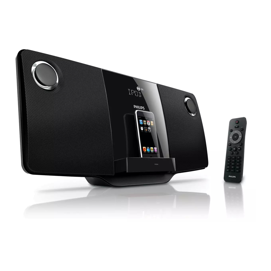
Micro Hi-Fi System
CONTENTS
Technical specification ..................................................................1-2
Service measurement setup..........................................................1-3
Service aids .................................................................................1-4
Instructions on CD playability ................................................2-1..2-2
Block diagram................................................................................3-1
Wiring diagram...............................................................................4-1
Disassembly diagram............ ........................................................5-1
Circuit diagram ..................................................................6-1..6-5
Layout diagram..................................................................6-6..6-7
MCU board
Circuit diagram .........................................................................7-1
Layout diagram..................................................................7-2..7-3
Display & Key board
Circuit diagram .........................................................................8-1
Layout diagram..................................................................8-2..8-3
Circuit diagram .........................................................................9-1
Layout diagram.........................................................................9-2
Ipod Jack & SW board
Circuit diagram .......................................................................10-1
Layout diagram....................................................................... 11-1
Exploded view diagram ...............................................................12-1
Mechanical parts list ....................................................................12-2
Electrical parts list...............................................................13-1..13-2
Revision list...................................................................................14-1
©
Copyright 2010 Philips Consumer Electronics B.V. Eindhoven, The Netherlands
All rights reserved. No part of this publication may be reproduced, stored in a retrieval
system or transmitted, in any form or by any means, electronic, mechanical, photocopying,
or otherwise without the prior permission of Philips.
Published by LX 1003 Service Audio
Version 1.2
All manuals and user guides at all-guides.com
Subject to modification
DCM276
-/05/55
3141 785 34202
Advertisement
Table of Contents

Related Manuals for Philips DCM276


Summary of Contents for Philips DCM276
-
Page 1: Table Of Contents
Revision list...................14-1 © Copyright 2010 Philips Consumer Electronics B.V. Eindhoven, The Netherlands All rights reserved. No part of this publication may be reproduced, stored in a retrieval system or transmitted, in any form or by any means, electronic, mechanical, photocopying, or otherwise without the prior permission of Philips. -
Page 2: Technical Specification
All manuals and user guides at all-guides.com 1 - 2 TECHNICAL SPECIFICATION Speakers Amplifier Speaker driver 4” woofer Total output power 2 x 5 W RMS Speaker impedance 5 W, 3 Frequency 125 Hz - 16 kHz, ± 3 dB response Signal to noise ratio >... - Page 3 All manuals and user guides at all-guides.com MEASUREMENT SETUP Tuner FM Bandpass LF Voltmeter 250Hz-15kHz e.g. PM2534 e.g. 7122 707 48001 RF Generator e.g. PM5326 S/N and distortion meter e.g. Sound Technology ST1700B Use a bandpass filter to eliminate hum (50Hz, 100Hz) and disturbance from the pilottone (19kHz, 38kHz). Tuner AM (MW,LW) Bandpass LF Voltmeter...
-
Page 4: Service Aids
All manuals and user guides at all-guides.com SERVICE AIDS WARNING All ICs and many other semi-conductors are susceptible to electrostatic discharges (ESD). Careless handling during repair can reduce life drastically. When repairing, make sure that you are connected with the same potential as the mass of the set via a wrist wrap with resistance. -
Page 5: Instructions On Cd Playability
All manuals and user guides at all-guides.com 2 - 1 INSTRUCTIONS ON CD PLAYABILITY Customer complaint "CD related problem" Set remains closed! check playability playability ok ? For flap loaders (= access to CD drive possible) "fast" lens cleaning cleaning method is recommended check playability playability... - Page 6 All manuals and user guides at all-guides.com 2 - 2 INSTRUCTIONS ON CD PLAYABILITY PLAYABILITY CHECK LIQUID LENS CLEANING Before touching the lens it is advised to clean the surface of the lens by blowing clean air over it. For sets which are compatible with CD-RW discs This to avoid that little particles make scratches on use CD-RW Printed Audio Disc ....7104 099 96611 the lens.
-
Page 7: Block Diagram
All manuals and user guides at all-guides.com SET BLOCK DIAGRAM... -
Page 8: Wiring Diagram
All manuals and user guides at all-guides.com SET WIRING DIAGRAM... - Page 9 All manuals and user guides at all-guides.com...
- Page 10 All manuals and user guides at all-guides.com CIRCUIT DIAGRAM - MAIN BOARD PART 1...
- Page 11 All manuals and user guides at all-guides.com CIRCUIT DIAGRAM - MAIN BOARD PART 2...
- Page 12 All manuals and user guides at all-guides.com CIRCUIT DIAGRAM - MAIN BOARD PART 3...
- Page 13 All manuals and user guides at all-guides.com CIRCUIT DIAGRAM - MAIN BOARD PART 4...
- Page 14 All manuals and user guides at all-guides.com CIRCUIT DIAGRAM - MAIN BOARD PART5...
- Page 15 All manuals and user guides at all-guides.com LAYOUT DIAGRAM - MAIN BOARD AND SOME SMALL BOARD TOP SIDE...
- Page 16 All manuals and user guides at all-guides.com LAYOUT DIAGRAM - MAIN BOARD AND SOME SMALL BOARD BOTTOM SIDE...
- Page 17 All manuals and user guides at all-guides.com CIRCUIT DIAGRAM - MCU BOARD...
- Page 18 All manuals and user guides at all-guides.com LAYOUT DIAGRAM - MCU BOARD TOP SIDE...
- Page 19 All manuals and user guides at all-guides.com LAYOUT DIAGRAM - MCU BOARD BOTTOM SIDE...
- Page 20 All manuals and user guides at all-guides.com CIRCUIT DIAGRAM - DISPLAY BOARD AND KEY BOARD...
- Page 21 All manuals and user guides at all-guides.com LAYOUT DIAGRAM - DISPLAY BOARD...
- Page 22 All manuals and user guides at all-guides.com LAYOUT DIAGRAM - KEY BOARD...
- Page 23 All manuals and user guides at all-guides.com CIRCUIT DIAGRAM - POWER BOARD...
- Page 24 All manuals and user guides at all-guides.com LAYOUT DIAGRAM - POWER BOARD...
- Page 25 All manuals and user guides at all-guides.com 10-1 10-1 CIRCUIT DIAGRAM - iPod JACK BOARD...
- Page 26 All manuals and user guides at all-guides.com 10-2 10-2 LAYOUT DIAGRAM - iPod JACK BOARD...
- Page 27 All manuals and user guides at all-guides.com 11-1 11-1 CIRCUIT DIAGRAM - SW BOARD LAYOUT DIAGRAM - SW BOARD...
- Page 28 All manuals and user guides at all-guides.com 12-1 12-1 SET EXPLODED VIEW...
- Page 29 SPEAKER 4" 5W 3 (SINGLE) T301 ! 996510026747 TRANSFORMER EI57 230V (-/05) T301 996510029315 TRANSFORMER 127/240V (-/55) SW01 996510011384 SWITCH SL1-22-62F-4W (-/55) AC01 994000001478 AC PLUG ADAPTOR (-/55) -/55 0001 996510029317 PCBA-MAIN "DCM276/55" 0002 996510029314 PCBA-POWER "DCM276/55" 0007 996510029311 PCBA-MCU (-/55)
-
Page 30: Main Board
All manuals and user guides at all-guides.com 13 - 1 ELECTRICAL PARTSLIST MAIN BOARD ASSEMBLY USB901 996510026748 USB SOCKET 4P USB-1400-060-010 X101 996500042441 X'TAL 32.768KHZ -20PPM X801 994000004551 CRYSTAL 16.9344MHZ +-20PPM JK902 994000004369 PHONE JACK TC38-063-05-0 JK903 996510012048 PHONE JACK D3.6mm P801 996510023905 OPTIC SENSER FM-9038TM2-5AN... - Page 31 All manuals and user guides at all-guides.com 13 - 2 ELECTRICAL PARTSLIST SW BOARD ASSEMBLY S801 994000004552 DETECT SWITCH S802 994000004552 DETECT SWITCH IPOD JACK BOARD ASSEMBLY IPOD901 996510018114 IPOD SOCKET 0.5MM 30P 180C MCU BOARD ASSEMBLY IC191 996510015481 IC HT1381 IC601 996510020772 IC SI636165TS...
-
Page 32: Revision List
All manuals and user guides at all-guides.com 14-1 REVISION LIST Version 1.0 (314178534200) * Initial Release Version 1.1 (314178534201) * P12-2 :AC cord set (-/55) 12NC is changed Added SCREW (accessory). V Version 1.2 (314178534202) * P12-2 :Change LEFT and RIGHT SPK Front for both /05 and /55;...
Need help?
Do you have a question about the DCM276 and is the answer not in the manual?
Questions and answers