
Summary of Contents for GM International D1049S
- Page 1 D1049S INSTRUCTION & SAFETY MANUAL SIL 3 Digital Output Driver NE Loads Bus Powered DIN-Rail Model D1049S D1049 - SIL 3 Digital Output Driver NE Loads Bus Powered ISM0097-9...
-
Page 2: Technical Data
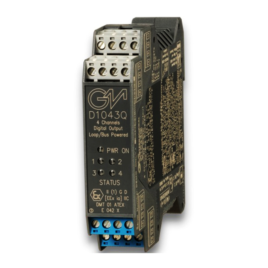
Characteristics General Description: The single channel DIN-Rail Bus Powered Digital Output Isolator, D1049S, is suitable for driving solenoid valves, visual or audible alarms to alert a plant operator, or other process control devices in Hazardous Area from a driving signal in Safe Area. It can also be used as a controllable supply to power measuring or process control equipment. -
Page 3: Ordering Information
Ordering information Power Bus and DIN-Rail accessories: Model: D1049S DIN rail anchor MCHP065 DIN rail stopper MOR016 Terminal block male MOR017 Terminal block female MOR022 Power Bus enclosure Front Panel and Features SIL 3 according to IEC 61508:2010 Ed. 2 for Tproof = 12 / 20 yrs (≤10% / >10 % of total SIF). - Page 4 Parameters Table In the system safety analysis, always check the Hazardous Area/Hazardous Locations devices to conform with the related system documentation, if the device is Intrinsically Safe check its suitability for the Hazardous Area/Hazardous Locations and gas group encountered and that its maximum allowable voltage, current, power (Ui/Vmax, Ii/Imax, Pi/Pi) are not exceeded by the safety parameters (Uo/Voc, Io/Isc, Po/Po) of the D1049 Associated Apparatus connected to it.
-
Page 5: Function Diagram
NON HAZARDOUS LOCATIONS, CLASS I, DIVISION 2, CLASS II, DIVISION 1, GROUPS E, F, G, CLASS III, DIVISION 1, GROUPS A, B, C, D T-Code T4, CLASS I, ZONE 2, GROUP IIC T4 CLASS I, ZONE 0, GROUP IIC MODEL D1049S Out 1 Solenoid Valve... - Page 6 Description: The D1049S is a single channel digital output drivers, Bus powered for NE (Normally Energized) loads. The Safety PLC or DCS control signal enables the field devices through the single channel digital output driver D1049S (1 intrinsic safety channel, Bus Powered), which provides the electrical isolation between Supply - Input and Output. The presence of the input control signal is also indicated by a yellow LED on the front panel.
-
Page 7: Installation
Consider the configuration setup defined in the previous proof test step (2) and change the SW1-1 DIP-switch from the OFF to the ON position, in order to enable the field line and load fault detection. Supply the D1049S module at 24 Vdc, apply a 24 Vdc = ON control signal to the module input channel, then connect an ohmmeter to the fault output and another one to the Fault Bus output. -
Page 8: Operation
Its use is allowed in applications requiring up to SIL 3 level (according to IEC 61508) in safety related systems for high risk industries. The Safety PLC or DCS driving signal controls the field device through the D1049S, which provides isolation and is capable of monitoring the conditions of the line. - Page 9 Configuration Configuration DIP switches are located on component side of pcb. These switches allows the configuration of phase reversal, override input and fault detection functions. Side B Panel View SW1 dip switch configuration SW1 factory settings All DIP-switches are ON Not used Field line and Disabled...
Need help?
Do you have a question about the D1049S and is the answer not in the manual?
Questions and answers