Advertisement
Available languages
Available languages
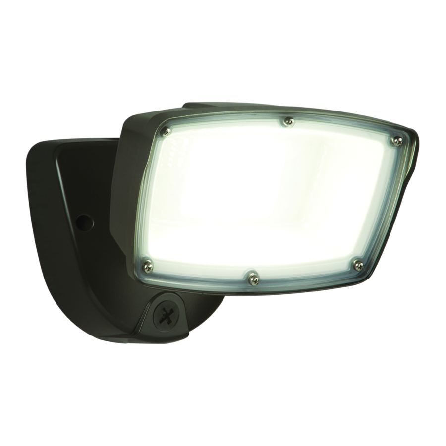
FSL503TIB
FSL503TIW
ENGLISH
ITEMS REQUIRED
(Purchase separately)
• Phillips screwdriver
• Weatherproof silicone caulk
IMPORTANT SAFETY INSTRUCTIONS
When using product, basic precautions should always be followed, including the following:
• Heed all warnings, including below warnings AND those included on product.
• Save these instructions and warnings.
• For outdoor use only.
• cULus LISTED for wet location.
• Disassembling your fixture will void the warranty.
• Your fixture is prewired and preassembled for easy installation.
• Read and follow these instructions.
• Risk of fire/electric shock. If not qualified, consult an electrician.
• Disconnect power at fuse or circuit breaker before installing or servicing.
CAUTION
• Connect fixture to a 120V-277V volt, 60 Hz power source. Any other connection voids
the warranty.
• Fixture should be installed by persons with experience in household wiring or by a
qualified electrician. The electrical system, and the method of electrically connecting
the fixture to it, must be in accordance with the National Electrical Code and local
building codes.
• Fixture designed for wall or eave mount to a junction box only. Mount fixture to a
grounded, recessed-mounted standard junction box marked for use in wet locations.
• Fixture can be mounted to an outdoor rated surface mount junction box or when used
with the included adaptar plate kit. See kit instructions for proper installation methods.
• This equipment has been tested and found to comply with the limits for
a Class B digital device, pursuant to Part 15 of the FCC Rules. These limits are de-
signed to provide reasonable protection against harmful interference in a residential
installation. This equipment generates, uses and can radiate radio frequency energy
and if not installed and used in accordance with the instructions, may cause harmful
interference to radio communications. However, there is no guarantee that interfer-
ence will not occur in a particular installation. If this equipment does cause harmful
interference to radio or television reception, which can be determined by turning the
equipment off and on, the user is encouraged to try to correct the interference by one
or more of the following measures:
- Reorient or relocate the receiving antenna.
- Increase the separation between the equipment and receiver.
Questions?/¿Preguntas ? 1-800-334-6871 ConsumerProducts@ cooperlighting.com
PACKAGING CONTENTS/ CONTENIDO DEL PAQUETE
A. Light fixture
B. Mounting bracket
Appareil d'éclairage
Support de montage
Accesorio
Soporte de montaje
E. Adapter Plate Kit
F. Support hook
Plaque adaptatrice trousse
Crochet
Placa daptadora equipo
Gancho de soporte
C. Gasket
D. (2) #6-32 x 3/4 in. and (2) #8-32 x 3/4 in. junction box screws
(use the size that fits your junction box)
Joint
(2) vis nº 6 de 32 x 3/4 po et 2 vis nº 8 de 32 x 3/4 po pou
Junta
boîtier de jonction (choisissez la dimension convenant
à votre boîtier de jonction)
(2) Tornillos #6-32 x 3/4 pulg. y (2) tornillos #8-32 x 3/4 pulg.
para montaje de la caja de conexión (utilice el tamaño que mejor
se adecue a su caja de conexión)
G. (2) #8-32 x 1-1/4 in. cover
mounting screws
(2) vis de protection nº 8
de 32 x 1-1/4 po
(2) Tornillos #8-32 x 1-1/4 pulg.
de montaje de la cubierta
- Connect the equipment into an outlet on a circuit different from that to which the
receiver is connected.
- Consult the dealer or an experienced radio/TV technician for help.
WARNING: FCC Regulations state that any unauthorized changes or
modifications to this equipment not expressly approved by the manufacturer
could void the user's authorization to operate this equipment.
SAVE THESE INSTRUCTIONS.
FOR BEST RESULTS
• Install light 8-16 feet above the ground.
• Do not mount fixture close to reflective surfaces
such as windows, white walls, white surfaces
and water.
• When installing two fixtures on one switch,
make sure the switch is rated for at least a
1 A inductive load.
• When mounting coverplate, make sure the photo
sensor orientation is at the bottom.
• When mounting to a wall, make sure the fixture is
7 in. on center away from eave and 13 inches on
center away from inside corner of the exterior
wall (Fig. 1).
ADJUSTING THE COLOR TEMPERATURE (CCT)
• This product features selectable white color
tuning. Choose between three preset light colors
on the center dial of the base housing before,
during or after installation (fig. 2):
• These settings are designated by the abbreviations
located on the center dial on the base housing
(fig. 2):
3K = 3000K CCT, or soft white
4K = 4000K CCT, or neutral white
[factory default]
5K = 5000K CCT, or daylight
• Use a flathead or Phillips head screwdriver to rotate the
dial so the arrow points toward the desired setting.
• DO NOT USE a power tool or over-rotate the dial.
MOUNTING AND WIRING YOUR FIXTURE
WARNING: Risk of electric shock. Disconnect
power at fuse or circuit breaker before installing
or servicing.
NOTE: Fixture can be wall or eave mounted (Fig. 3).
1
Instruction Manual
/ Instrucciones
H. (2) Decorative screw cover caps
(2) cache-vis décoratifs
(2) Cubiertas tapatornillos decorativas
1
7 in.
13 in.
13 in.
2
3
Wall mount
Eave mount
Advertisement
Table of Contents

Related Manuals for Halo FSL503TIB

Summary of Contents for Halo FSL503TIB
- Page 1 F. Support hook H. (2) Decorative screw cover caps mounting screws Plaque adaptatrice trousse Crochet (2) cache-vis décoratifs FSL503TIB (2) vis de protection nº 8 Placa daptadora equipo Gancho de soporte (2) Cubiertas tapatornillos decorativas FSL503TIW de 32 x 1-1/4 po (2) Tornillos #8-32 x 1-1/4 pulg.
-
Page 2: Troubleshooting
PART 2: ATTACHING FLOOD LIGHT FIXTURE TO ADAPTER PLATE NOTE: Coverplate mounts to recessed mounted 1-1/2 in. 1-1/2 in. standard junction boxes (Fig. 4). Junction box must be 6. Peel off the adhesive side of the gasket included Fig. 3 at least 1-1/2 inch in depth for proper installation for with the fixture and place on top of the adapter recessed mount application. - Page 3 • Lors de l’installation de la plaque du couvercle, • Detailed description of problem assurez-vous que le photodétecteur est orienté All returned products must be accompanied by a Return Goods Authorization Number issued vers le bas. by the Company and must be returned freight prepaid. Any product received without a Return 18cm •...
-
Page 4: Dépannage
DÉPANNAGE 7. Rebranchez l’électricité au disjoncteur principal. Problème Cause / Solution La lumière ne Le luminaire n’est pas sous tension. s’allume pas.. • Vérifiez que le disjoncteur n’a pas été déclenché. • Vérifiez que l’interrupteur est allumé. L’appareil d’éclairage détecte la lumière du jour. •... - Page 5 ubicadas en el cuadrante central en la cubierta de la ESPAÑOL base (figura x): 3K = 3000K CCT, o blanco cálido (warm white) ARTÍCULOS NECESARIOS 4K = 4000K CCT, o blanco neutro (neutral white) Este es el valor predeterminado de fábrica (se compran por separado) 5K = 5000K CCT, o blanco frío (cool white) •...
-
Page 6: Diagnostico Y Solucion De Problemas
CAJAS DE LUMINARIAS DE MONTAJE EN SUPERFICIE PARA DIAGNOSTICO Y SOLUCION DE PROBLEMAS PAREDES Y ALEROS Fig. 1 Problema Causa Posible/Acción Correctiva Para usas con caja de luminaria redonda de 4 in 1. Determine la orientación adecuada de la placa El accesorio se El detector de luz está...
Need help?
Do you have a question about the FSL503TIB and is the answer not in the manual?
Questions and answers