Table of Contents
Advertisement
Available languages
Available languages
Quick Links
LED ECO
NOTE: Keep your receipt and these instructions for proof of purchase.
WARNING: Shut off the power at the circuit breaker or fuse panel before removing the
old fixture, ballast, or fluorescent tubes.
If you are unfamiliar with electrical installations, we recommend you contact a qualified
electrician to do the installation.
NOTE: Two people are recommended for installation of this light fixture.
NOTICE: Select a suitable location that can support the weight of the fixture. Determine
the method of mounting before beginning installation.
CAUTION: Installer is responsible to ensure grid location is rated for fixture weight
prior to installation. If uncertain, use cable to support fixture from the retention clips to
a suitable support structure. Failure to do so can cause serious injury.
Shut off power at the electrical panel before beginning the installation.
1
Remove existing fixture and set aside to recycle in accordance with local
2
requirements.
Choose your favorite correlated color temperature (CCT) before installing the fixture.
3
Left to right: 3500K/4000K/5000K
NOTICE: The factory setting for the correlated color temperature (CCT) is 3500K,
which is the warmest white light.
Choose the desired brightness (lumen output).
4
NOTICE: The factory setting for the brightness (lumen output) is 4500lm (Mode #
64222202 64222201, and 6250lm (Model # 64224202 & 64224201).
MAKING ELECTRICAL CONNECTIONS
Remove the driver box cover plate and punch out the knock out hole.
5
Feed the conduit or Romex (based on local electrical code) through the knock out hole.
6
NOTE: It's recommended to use 16GA pigtails from the terminal block to the
respective power supply wires. Must add pigtail or jumper wires into the ACL and ACN
terminal to use a wire larger than 16AWG for both AC and Neutral Line.
Make the electrical connections:
7
Connect black (L) wire with black wire in the driver.
Connect white (N) wire with white wire in the driver.
Connect ground wire with yellow wire in the driver.
If a 0-10v dimming circuit is available, connect fixture purple wire to driver DIM+ and
gray fixture wire to driver DIM-.
Tuck wires inside the driver box and reattach the driver cover.
8
GRID CEILING INSTALLATION
Mounting Clip
9a
CAUTION: Clip is used for positioning
(NOT for mounting)
Bend each of the mounting clips on the back of
the fixture upward and then twist the top 90°.
Place the fixture into the ceiling grid, hook the
mounting clips over the grid ceiling supports
and make sure it is secure.
Model # 64222201
USE AND CARE GUIDE
9
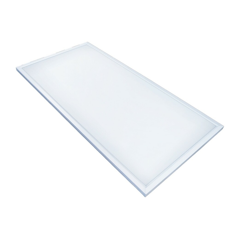
FLAT PANELS WITH LUMEN BOOST™ AND COLOR PREFERENCE
SUSPENSION MOUNTING
Depending on mounting location, install 4 toggle bolts
9b
into drywall or 4 hook screws into wood.
NOTICE: Toggle bolts are not considered an acceptable
means of support in Canada, in accordance with CSA
C22.2 No. 250.4.
NOTICE: There are many installation applications to
suspension mount the fixture. Installer is responsible
to ensure mounting accessories and hardware are
compatible with attachment method to surface
or structure in accordance with any local code
requirements for installation and inspection.
Attach the aircraft cable to the toggle bolts or hook
10b
screws.
Part # FPCP-2X2-4500LM-8-CP3-MV-LVD-1PK
64222202
FPCP-2X2-4500LM-8-CP3-MV-LVD-2PK
64224201
FPCP-2X4-6250LM-8-CP3-MV-LVD-1PK
64224202
FPCP-2X4-6250LM-8-CP3-MV-LVD-2PK
PACKAGE CONTENTS
Part
Description
A
Fixture*
* 2x2 Flat Panel model numbers: 64222201, 64222202
* 2x4 Flat Panel model numbers: 64224201, 64224202
HARDWARE AVAILABLE TO PURCHASE
Hardware kits for surface mounting and suspension
mounting are sold as separate accessories. Please contact
ETiSSL Customer Service 1-855-384-7754 for additional
information.
Part
Description
AA
Aircraft Cable for Suspension Mounting
BB
Surface Mounting Kit for 2' x 2' Flat Panel
CC
Surface Mounting Kit for 2' x 4' Flat Panel
x 2
Panel
AA
Quantity
1
Surface Mounting Kits - BB and CC
AA
Yellow
Black
White
Purple 0-10v Dim+
Gray 0-10v Dim-
Quick Cable Lock
AA
Mounting Clips
Bend each of the mounting clips on the back of
11b
the fixture upward.
Connect the mounting clips to the aircraft cables
by using S hooks.
Adjust the aircraft cables to level the fixture.
NOTICE: The LED flat panel must hang a
minimum of 3 in. from the ceiling.
Make the electrical connections. See Making
12b
Electrical Connections.
Restore power at the electrical panel.
13b
Turn on the light switch to activate the fixture.
Certification # 64222201
64222202
64224201
64224202
®
A
A
Quantity
Part #
2
95457326101
1
70303122
1
70303124
x 2
x 12
x 2
x 4
Switch
A
Advertisement
Table of Contents

Summary of Contents for Et 64222201
- Page 1 Choose the desired brightness (lumen output). NOTICE: The factory setting for the brightness (lumen output) is 4500lm (Mode # 64222202 64222201, and 6250lm (Model # 64224202 & 64224201). MAKING ELECTRICAL CONNECTIONS Remove the driver box cover plate and punch out the knock out hole.
- Page 2 SURFACE MOUNTING Use screws to assemble 3 sides of the If installing into drywall, drill four 1/4 in. diameter Slide the fixture into the surface mounting surface mounting kit. holes into the ceiling, insert drywall anchors into kit and use screws to secure the remaining the holes, and use screws to secure the surface piece of the surface mounting kit.
- Page 3 NOTE : On recommande d’utiliser des queues-de-cochon de 16GA du bornier aux Blanc fils d’alimentation respectifs. Il faut ajouter une queue-de-cochon ou un fil volant aux Interrupteur bornes ACL et ACN pour utiliser un fil de calibre supérieur à 16AWG pour le câble CA et Violet 0-10v Dim+ neutre. Panneau Gris 0-10v Dim- Effectuez les connexions électriques :...
- Page 4 Il n’est toutefois pas garanti qu’aucune interférence ne surviendra dans une installation particulière. Si le dispositif cause une interférence nuisible à la réception radio ou télé, ce qui peut être établi en éteignant et rallumant le dispositif, on conseille à l’utilisateur de tenter de remédier à...
- Page 5 Elija el brillo deseado (lúmenes). AVISO: La configuración de fábrica para el brillo (salida de lúmenes) es 4500 lm (modelos # 64222202 64222201) y 6250 lm (modelos # 64224202 y 64224201). HACER LAS CONEXIONES ELÉCTRICAS Retire la placa de cubierta de la caja del controlador y perfore el agujero ciego.
- Page 6 MONTAJE EN SUPERFICIE Use tornillos para ensamblar 3 lados del Para paneles de yeso, taladre cuatro orificios de 1/4 Deslice la luminaria en el kit de montaje en kit de montaje en superficie. pulg. de diámetro en el techo, inserte anclajes de superficie y use tornillos para asegurar la paneles de yeso en los orificios y use tornillos para pieza restante del kit de montaje en superficie.
Need help?
Do you have a question about the 64222201 and is the answer not in the manual?
Questions and answers