
Related Manuals for Hallowell H-Post Shelving

Summary of Contents for Hallowell H-Post Shelving
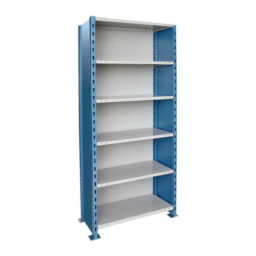
- Page 2 H-POST SHELVING INSTRUCTIONS 5133 5120 SHELF CLIP BACK PANEL CLIP 5027 COMBINATION CLIP 5025 FOOT PLATE 5003-hh 5138-wwdd H-POST SHELF 5115 5342-xx DOUBLE 5344-dd BACK SWAY BRACE CONNECTOR STRIP SIDE SWAY BRACE 5114 5096-ddhh SINGLE 5111-wwhh SIDE PANEL CONNECTOR STRIP...
- Page 3 INDIVIDUAL AND STARTING UNITS OPEN TYPE SIDE BRACES 1. Assemble (2) post sections by attaching side sway braces to posts at location "A" shown in Fig. 1. Place sway braces regarding H-Post length and measurement "A". 27.00 Post Length "A" 7'3"......28-3/8"...
- Page 4 Step 2 and insert top and bottom shelves. Attach sway braces to post connectors as per Step 4. FIGURE 5 NOTE: Hallowell H-Post Shelving construction in seismic areas may require different brace PG. 2 placement, please contact the factory for details.
- Page 5 SWAY BRACE Back-to-Back Units 1B. Assemble post and side sway braces for (2) units as per step 1. Add post combination clips as per step 3. Add shelves as per step 2. Stand units and push together so that post FIGURE 6 connectors are in aligment.
-
Page 6: Back Panels
NOTE: In some requirements, Back Panel Connector Strip may be used rather than Combination Clip in back-to-back units. In those cases, see Figure 12 for attachment details. Consult with Hallowell to determine the components supplied. FIGURE 13 PG. 4... -
Page 7: Back Panel
In FIGURE 14 thise cases, see Figure 14 for attachment details. Consult with Hallowell to dtermine components supplied. Post Splice 5010 1Q. Insert post splice into top of lower post POST SPLICE so that the "Y"...
Need help?
Do you have a question about the H-Post Shelving and is the answer not in the manual?
Questions and answers